
| Home / Section index | www.icosaedro.it | |
 Celestial Navigation at Home
|
Updates: 2019-06-23 Fixed Bennett's formula for refraction correction. |
In this article we show how it is possible to determine our own position on the Earth by using simple tools available at home and some calculations. Our purpose is merely educational and our self-made tools very basic, but despite that we will determine our position with an accuracy of few tens of Km.
The position of the celestial bodies in the sky can be predicted with extreme accuracy by calculation. The positions of these of all main celestial bodies (Sun, Moon, stars and planets) are calculated and published year by year for the needs of the celestial navigation. So, given day, time and location on the Earth, the position on the sky of any of these celestial bodies can be determined.
The vice-versa is also possible too: given day, time and the position of the celestial bodies in the sky, it is possible to determine our own position on the Earth. How this can be made is the subject of this article.
Be S the position on the Earth of a certain celestial body at a given day and time, and be P our position. An observer located in S will see the celestial body over its head, that is at its Zenith. From our position in P we will see the light of the celestial body coming from the same exact direction, but at a certain angle from our Zenith; this angle is named Zenith distance of the celestial body and indicated as ZD.

Since the celestial bodies are so far away from the Earth, rays coming from them are practically parallel. Looking at the figure above, the local vertical line in P crosses the parallel rays coming from the celestial body, and then the ZD angle as seen from P is also the angular distance of P from S respect to the center of the Earth O. If the Earth is a perfect sphere of radius R, the distance of P from S is then R*ZD. Since the position of S is known from the nautical almanac, we now know we are somewhere at that distance from S.
For example, suppose we measured ZD=27 DEG for some celestial body. Assuming R=6371 Km be the radius of the Earth, it follows that our distance from S is R*ZD = 6371 Km * 27 DEG = 6371 Km * 27 * π/180 = 3002 Km. Taking a world map, opening a divider to that calculated distance and pointing in S, we may draw a circle like in the figure below:

This circle is named line of position or LOP and includes all the locations on the Earth from which the celestial body distance from the Zenith appears to be 27 DEG. Our position P is then somewhere over this circle. But where exactly? To solve this problem we may take a second celestial body, measure its ZD, and draw a second LOP over the same world map just like we did before. The result is depicted in the figure below.

We now have 2 LOPs and 2 intersections A and B, then our position P must be either A or B. This ambiguity can be solved in several ways:
Sometimes we don't have the chance to do several sightings. For example, by day time typically only the Sun is available on the sky, so we must stick with that alone. How do we do then? Several ways:
There are still some practical problems to solve. How to measure the ZD of a celestial body? How to draw a circle on a world map, given the distortions of the sphere projected on the flat paper? And how to numerically calculate the intersections between LOPs?
Aboard of a moving vehicle it's hard to determine the local vertical direction because of the movements and shaking of the moving vehicle. Aircraft could have an inertial system gyroscopically stabilized to provide the Zenith direction. Aboard of a ship, using the sextant is normally preferred. The sextant measures the angular distance between two objects, for example between a celestial body and the far horizon. Since the horizon could be hard to see at night, the sextant is mainly used for Sun observations in daylight. The angular distance of a celestial body from the horizon is named elevation (ELEV). The relationship between the elevation ELEV and the Zenith distance ZD is very simple, their sum being a right angle:
ZD + ELEV = 90 DEG
from which we get the conversion formulas between ZD and ELEV:
ZD = 90 DEG - ELEV
ELEV = 90 DEG - ZD
The sextant can be used on land as well through an artificial horizon. The artificial horizon is a small basin filled with some fluid, like water or oil. We then measure the angular distance between the direct sight of the celestial body and its image reflected in the basin. Since the surface of the fluid lies on a plane perpendicular to the local vertical, the light reflected from the fluid and the direct light are separated by an angle which is exactly two times the elevation (see the figure below).

By looking inside the sextant, the observer will see the upside-down image of the Sun to the left as reflected by the fluid, and the direct image of the Sun to the right as reflected by the mirrors of the instrument. Rather than trying to align the centers of the two images, it could be easier to align the upper limb of the Sun on the left with the lower limb to the right; the read angle must be divided by two and the semi-diameter of the Sun must be subtracted (15 arc minutes, or 0.25 DEG) to get the elevation.
But we don't have a sextant, and we mostly live on the land, so we need something simpler and more practical. We need an astrolabe.
Our "astrolabe" will be a protractor to measure the elevation of the Sun over the horizon. The same instrument could be used to measure the elevation of any other celestial body as well, but its aiming device will be specifically customized for the Sun only.
We could use any piece of thin cardboard, the kind of cardboard used for food and dress packaging for example. Using a pencil, draw a perfect square shape about 200 mm large. The exact dimension does not care, but it's important be perfectly square, so ensure its sides are all equal, and the two diagonals are perfectly equal. Now take a divider open to the same size of a side and draw a 90 DEG arc around the top-right vertex of the square (figure A).


Figure A, B and C.
Keeping the divider open at the same exact width and pointing the lower-right and upper-left vertices of the square, draw the 30 and 60 DEG mark points. Use a ruler to draw the 3 chords of the 30 DEG angles; the middle points of these chords allows to draw further 15 DEG angle marks. In this way the right angle of 90 DEG is now divided into 6 arcs 15 DEG wide each.
Draw the chords of each 15 DEG arc (figure B). Since these chords approximate quite well their respective arcs, we may use the ruler to draw 15 equally spaced degree marks within these straight short segments. One may calculate that these equally spaced degree marks approximate the real marks quite well, the error being no more than ±0.017 DEG. Since our readings of the scale cannot be more accurate than 0.5 or, at most, 0.2 DEG, this division error is perfectly acceptable. The figure shows the division process of a single 15 DEG arc; proceed the same way with the other arcs. The figure C is our protractor scale completed.
If a single layer of cardboard is too flexible, we can glue a second layer separated by 4 or 5 rings made of thin stripes of the same cardboard.
To complete our instrument, we add a pivot pin point to the upper-right corner of the square; we could use a paper clip for that. This pivot point will support a plumb-line made of a string and some weight -- a metal washer or a nut will do. Finally, an "L" shaped piece of cardboard glued near the upper-left corner will be the screen where the Sun will project the shadow of the pivot pin; remember to draw a reference line perfectly aligned with the upper side of the square. The figure below shows our completed astrolabe.

Keep the flat surface of the astrolabe perfectly vertical, so that the string of the plumb-line may oscillate freely back and forth few millimeters away from the protractor scale. Tilt up the astrolabe toward the Sun until the shadow of the pivot pin appears on the screen; adjust the tilt angle until the shadow is perfectly aligned with the reference line drawn on the screen. The plumb line may oscillate for a while, and it could be necessary to dump a bit these oscillations. Check again the alignment of the pivot pin shadow with the mark line on the screen and read the tilt angle indicated by the string of the plumb line over the protractor scale. Although our scale only reports integral degrees, fractions of a degree could be estimated and an accuracy of at least 0.5 DEG or maybe even 0.2 DEG can be attained. Take note of this angle along with the UTC time of the observation. The UTC time is the wall clock time minus the local time zone and minus the possible time saving hour. A sample reading could look like this:
| UTC | Star | Lat | Lon | Elev |
|---|---|---|---|---|
| 2018-10-18 09:51:30 | sun1 | 33.0 | ||
| 2018-10-18 12:12:30 | sun2 | 32.8 |
From the web site TheNauticalAlmanac.com download the Sun ephemeris for the year 2018 in PDF format, compact version. Go to the page marked "2018 October 13 to Oct. 27" and locate the day 18:
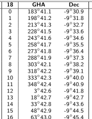
The table lists the positions of the Sun at integral hours of the day. At hour 9, the Sun GHA is 318 degrees and 42.2 primes, and its declination is -9 degrees and 39.1 primes. The declination is the latitude of the Sun. It is convenient to express the latitude as a simple number with decimals dividing the arc primes by 60, so obtaining a latitude of -9.65 DEG. Two decimal figures are more than enough for our needs.
The GHA is the Greenwich Hour Angle, that is the longitude measured starting from the Greenwich meridian and continuing toward West, and completing a full 360 degrees turn around the world back to the Greenwich meridian again. Here too, it is convenient to express this angle as a simple number with decimals, so obtaining GHA 318.70 DEG. The GHA equals the longitude for values up to 180 DEG; for GHA greater than that, 360 DEG must be subtracted:
lon = GHA for GHA up to 180 DEG
lon = GHA - 360 for GHA beyond 180 DEG
In our case the longitude of the Sun is then lon = -41.30 DEG.
We proceed the same way for hours 10, 11, 12 and 13, so obtaining the following table:
| Hour | Lat | Lon |
|---|---|---|
| 9 | -9.65 | -41.30 |
| 9.51 | -9.66 | -33.65 |
| 10 | -9.67 | -26.30 |
| 12 | -9.70 | +3.71 |
| 12.21 | -9.70 | +6.86 |
| 13 | -9.71 | +18.71 |
The rows highlighted in yellow color have the fractional hour of our sighting reported, and the latitude and longitude of the Sun at that time calculated by interpolation of the closest values available from the ephemeris. Here are the formulas we used:
fractional_hour = minutes/60 + seconds/3600
interpolated_value = (value_after - value_before) * fractional_hour + value_before
For example, the sighting time of our first observations 09:51:30 becomes the decimal hour 9.51; the interpolated values for the latitude and longitude of the Sun at that moment are:
lat = (-9.67 + 9.65) * 0.51 - 9.65 = -9.66
lon = (-26.30 + 41.30) * 0.51 - 41.30 = -33.65
Pay attention to the signs of the numbers!
We can now finally complete the observations table by adding the coordinates of the Sun at times of the observations:
| UTC | Star | Lat | Lon | Elev |
|---|---|---|---|---|
| 2018-10-18 09:51:30 | sun1 | -9.66 | -33.65 | 33.0 |
| 2018-10-18 12:12:30 | sun2 | -9.70 | +6.86 | 32.8 |
We finally have all the data we need to solve our position: we have the coordinates of two celestial bodies (the Sun at different times), we have their elevation over the horizon and then their Zenith distances ZD, and we may then draw the respective lines of position LOP. To determine the intersections of these LOPs we may use two methods: the analog computer or the digital computer.
To build our analog computer we need the following tools:

Proceed as follows:
One of these two points can be rejected if we have a rough estimation of the azimuth of the Sun. For example, if the Sun direction was South, the point B can be rejected, then our position is A.
The intersections A and B of the LOPs can also be calculated numerically with greater precision by using the celestial navigation computer page. Enter the name of the observation (for example sun1 and sun2), the latitude and the longitude of the celestial body, and the measured elevation:
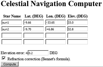
The refraction correction should always be enabled, especially for elevation angles below 10 DEG. Finally, press the Compute button. The JavaScript code inside the page will calculate and display the calculated intersections:
sun1-sun2-A = lat 44.422 ± 0.219, lon -13.674 ± 0.689
sun1-sun2-B = lat -65.030 ± 0.219, lon -14.093 ± 1.166
and will display the respective LOPs:
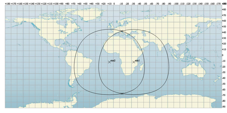
One of these two fix points can be rejected if we have a rough estimation of the azimuth of the Sun. For example, if the Sun direction was South, the point "sun1-sun2-B" can be rejected, then our position is "sun1-sun2-A". Finally, our fix point is lat 44.392 ± 0.219, lon -13.679 ± 0.689. Note the error, which is estimated based on the indicated elevation error we set in the input mask (a quite optimistic 0.2 DEG in this example).
The bad news: the Earth is not a sphere, but it has a much more complicated shape. Then all the argumentation we made above is, within some extend, wrong. The good news: latitude and longitude are defined in such a way that the exact shape of the Earth does not matter, and all the arguments above are still valid provided that they are made over latitudes, longitudes and Zenith distances only. Lets see why.
For the purpose of the navigation, the shape of the Earth can be represented by an ellipsoid, more precisely the WGS-84 ellipsoid. Latitudes and longitudes are always referred to this "nominal" shape of the Earth, both on navigation charts, GPS and calculations. The minor axis is the polar spin axis, and the major axis is the equatorial radius. The center of the WGS-84 ellipsoid is located at the gravitational center of the Earth.

The length of minor and major axis are defined in such a way that the surface of the WGS-84 ellipsoid matches nearly perfectly the sea level over the entire globe, at least within few tens of meters:
a = 6378137.0000 m
b = 6356752.3142 m
The meridian lines join the two poles; the longitude is the angular distance of a meridian from the zero reference meridian of Greenwich. No surprise here.
But the important fact in our discussion is the way the latitude has been defined. Given an arbitrary point P, the local vertical line is the normal line to the ellipsoid surface in A and crossing P. The latitude is the angle this vertical line PA forms with the equatorial plane. Note that the vertex of this angle is not the center of the ellipsoid, instead it is some point B that depends on the specific latitude. All that means the latitude and the longitude of any point P tell how the local vertical line is oriented respect to the equatorial plane and the polar axis.
So for example, the Polar Star has (about) ZD=0 DEG at the North Pole, and ZD=90-lat at any latitude lat. In other words, the Zenith distance of a celestial body is specific of the given latitude and longitude of the location, whichever the exact shape of the Earth could be.
Things go in a completely different way whenever linear distances have to be calculated among far points. Only in this case we must account for the non-sphericity of the Earth, and we must perform quite complex calculations over the WGS-84 ellipsoid to get accurate results.
| Umberto Salsi | Comments | Contact | Site map | Home / Section index |
Still no comments to this page. Use the Comments link above to add your contribute.