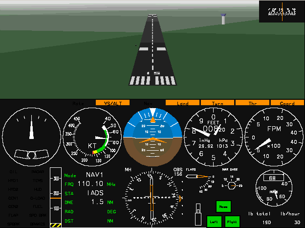
Screen shot (landing with the C-172 RG).
by Riley Rainey
updated by Umberto Salsi
Introduction
Features
Limitations
Support
Acknowledgments
Launcher interface
Command line options
Keyboard Commands
Abbreviations
Units of measurement
ACM is a distributed multiplayer air combat simulation program that runs on Linux and Windows. Players engage in air-to-air combat with infrared missiles and cannon, but civil aircraft are available too. Users can add more aircraft models and more sceneries, and this manual explains how to do that.
Aircraft are simulated as 6 degrees of freedom bodies, and every model gets described by its aerodynamic properties. Landing gear dynamics, engines, atmosphere properties and wind are also simulated, so you can experiment the different behaviors of the aircraft in different flight conditions.
The "world" of ACM is round, but the terrain is uniformly green and lacking of any detail apart the fog and some runway here and there. This poor rendering is intentional because it makes the program so light and fast, performing 25 frames per second with a CPU load nearly zero, without the need for an accelerated video-card nor specialized graphical library. ACM is also suitable for instrumental flight, since it provides many airports and related radio-navigation aids, including NDB, VOR, DME and ILS.
Screen shot (landing with the C-172 RG).
Summary of the main features currently implemented:
|
|
The source code of ACM is known to compile and run on these platforms: Linux Slackware 14.1 32-bits; Linux Slackware 14.2 64-bits; Windows 7 32-bits with MinGW; Windows 7 64-bits with MinGW. A binary executable package for Windows 32-bits is also available; that package runs on Windows 64-bits in compatibility mode.
News, bugs and updates for ACM are available at www.icosaedro.it/acm/download.html.
The original version of this program, ACM-5.0, was developed by Riley Rainey and distributed under the GPL license, and it is still available from Web Simulations Incorporated (www.websimulations.com).
The first version of ACM was released in 1991 via the venerable Usenet comp.sources.unix newsgroup. Since then, ACM has been upgraded to support the IEEE 1278 Distributed Interactive Simulation (DIS) protocol.
Multiplayer mode is supported through the DIS protocol. When all the computers participating to the simulation belong to the same subnet, the broadcast communication mode mode can be used, otherwise a relay server is also provided to relay packets over broader networks and possibly the Internet. ACM's DIS glue code was created by Mats Loftkvist.
Many others have generously supplied bug fixes and other changes to ACM-5.0 since it was originally released. In particular, Brad Bass and Tim Tessin contributed with their encouragement and continued support. Charlie Briggs and Tom Giertz have helped out a lot, too.
This manual documents ACM version 6, basically the ACM-5.0 version with some additions and corrections, more aircraft models both military and civil and more instrumentation for the pilot, and several other new features.
ACM is totally C source code and compiles under Linux 32 and 64 bits and under Windows with the MinGW system development kit.
You can start the program either from the command line or from the graphical interface. The ACM distribution package includes a simple launcher program to start ACM.
Windows users need to install the TCL/TK language interpreter from www.tcl.tk in order to execute this launcher interface. There are several implementations of the binary executable TCL/TK; one I found very easy to install is that provided by Magicsplat available at www.magicsplat.com/tcl-installer/index.html. Often these packages provide very advanced libraries and programs along with the basic Tcl/tk, but for our needs only a basic installation is enough.
Run the program acm.tcl by either double clicking on the icon or
issuing the command
$ ./acm.tcl
If your computer complains about the invalid path of the "wish"
interpreter (the Tcl/Tk window shell), simply open the file
acm.tcl with your text editor and change the first line so
that the file path will match the location of the "wish" interpreter on
your system. The windows can display several panels: select the desired
panel pressing the button at the top of the window.
Start from the Configuration panel. If this this is the first time you run the launcher, it is mandatory to check the correct configuration in the Configure panel as described below. Usually the launcher can figure out by itself the correct paths of the ACM executable program and of the objects directory, but in some cases human assistance is required :-)
The preferences you set in this mask are saved in the file
.acmtkrc in your home directory, and restored every time
you restart the program. The button Run starts ACM. The button
Default sets the default values into all the panels. The buttons
Quit (or the keyboard Esc key) exits the program saving the
contents of all panels; you may also click on the close window button.
This panel lets you to select your aircraft Model among those defined in the objects/aircraft.txt file.
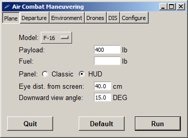
The Payload entry box allows to set the total payload of your craft; at least 200 lb should be accounted for the pilot and for each passenger; if left empty, the default is 150 lb.
The Fuel entry box allows to set how much fuel to load; if left empty, the default is the maximum allowed by the specific aircraft model.
The Panel radio buttons allows to choose among the classic instruments panel and HUD mode; once started, you can however switch between the two modes by pressing SHIFT-H.
The Eye dist. from screen allows to set the distance of your head from the screen, so an appropriate zoom factor can be calculated (more about this next).
The Downward view angle allows to set your downward visibility angle from the cockpit; usual values are about 10 degrees for civil aircraft and 15 degrees or more for modern jet fighters. The picture below illustrates these parameters:
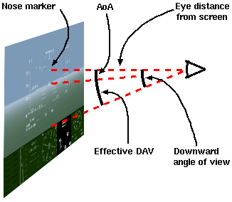
Scale factor and cockpit view layout.
From the distance of the eye from the screen the program compute a proper scale factor so that the landscape visible outside the cockpit can be rendered realistically and without distortion, a feature particularly useful in visual flight mode.
The downward angle of view (DAV) allows the pilot to see below the horizontal axis of the aircraft. This angle can range from 7 to 10° for civil aircraft, up to 15 or even 18° on fighters. Flying at low speed the angle of attack (AoA) reduces the visibility even more, and the effective downward angle of view becomes the difference DAV−AoA. To fully display the HUD graphics a DAV of at least 12° is required.
From this panel you may choose the departure location at the end of some runway, or enter a location by hand at an arbitrary geographical location.
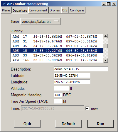
You may select the airport and the runway among the zones defined in the objects/zones.txt file and listed in the zones menu. Once the zone of your interest has been chosen, the full list of airports and runways is updated accordingly. By clicking on a runway, the latitude, longitude and heading fields below are set and a Description field is automatically generated. The altitude and initial speed gets blanked so that the aircraft can be gently deployed on the selected runway.
The initial location can also be entered manually and a corresponding description field can be freely edited. By entering a specific altitude, speed and heading, the aircraft starts airborne with the landing gear up and a pitch of 2 degrees nose up.
If all fields are left blank, the starting location is 0N 0S at sea level altitude...
The Time field allows to enter the departure date and time in OSP 8601 format, for example "2017-10-26T09:00". The time is "zulu", that is UT; there is no way to specify a time zone. For a complete list of other abbreviated syntaxes, type a random string and let the program complain: the error message will explain all the possible alternatives.
By leaving checked the now box, the program reads the current UT from the clock of your computer.
It is very important to correctly set the date and the time of the departure. In fact, the program calculates the Sun ephemeris for the day and adjusts the brightness of the scene accordingly. Moreover, the magnetic field on the Earth is calculated for the given date; you may experience how much the the magnetic field changes over time at any location of the Earth by entering different dates.
Use SHIFT-D to display state informations. At any time while you are flying, by pressing this keys combination, the state page is displayed with several useful informations, including: the aircraft model you are currently using; the current simulated zulu date and time; the current position; the current magnetic field variation VAR respect to the geographical north. Several other informations are there mostly for debugging and may not be of much interest for you.
This panel allows to set the weather conditions and some other environmental and rendering options.
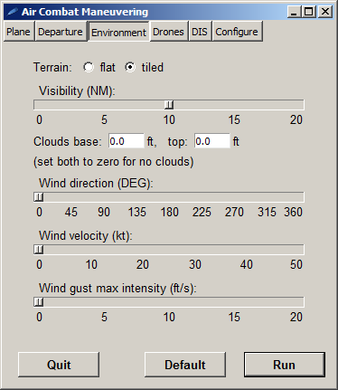
The Terrain radio buttons allows to choose among the flat terrain rendering (faster, but boring) and the tiled terrain rendering (nicer, but possibly slow on some very old computer with shared built-in video memory). The tiled mode is recommended as it gives a simple but still useful speed and orientation feeling while flying at low altitude. At high altitudes, or for combat maneuvering, probably the faster flat terrain rendering is preferable.
The Clouds base and top entry fields allow to set a tick layer of clouds. Clouds are opaque both to visible light and to the infra-red seekers of your missiles and those of the drones. No clouds are rendered if the top level is less or equal to the base level.
The current implementation of the DIS protocol ignores the clouds. ACM does not currently manages the environmental parameters over the DIS protocol, so daylight, wind and clouds have only a local effect and are not shared among the participants into the simulation. Then, for example, trying to hide yourself inside the clouds to escape an hostile missile aiming at you fired by a remote player, does not work because the remote missiles are guided by the remote program where probably the player has set clear skis...
The Wind direction if the geographic (NOT magnetic) direction from which the wind blows. The Wind velocity parameter is self explanatory. The Wind gust max intensity adds some horizontal random, rapidly varying, component to the wind velocity to make things more interesting.
You may practice with ACM (air combat maneuvering) techniques also alone by fighting against the robots driven by the program itself. Up to 31 drones can be generated by simply pressing the l key, but typically just one is challenging enough.
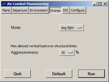
Drones can be generated in either "dog fight" or "hunting" mode. In dog fight mode, drones are placed just in front of you. In hunting mode, drones are placed up to 50 NM away from you in a random direction and altitude.
This panel allows also to set the drones aggressiveness, that is how much "G"s they will pull to escape from you or to attack you. For example, by selecting 50% aggressiveness, drones will maneuver up to the 50% of their maximum structural vertical load, both positive and negative. Your airplane undergoes to the same structural limitations, so always put an eye on the G-LOAD light of the warning panel or you will loose your plane!
The distributed interactive simulation protocol (DIS) is a standard network protocol born to simulate war sceneries involving any type of known submarine, ship, land vehicle, aircraft, missile, space vehicle and munition, both civil or military. The ACM program uses that same protocol to share its local entities with other ACM programs running on other computers, or even other instances of the ACM program running on a single computer.
The DIS protocol feature can be disabled, or operating on a local network (LAN) using the broadcast protocol, or operating on a wide area network (WAN) like Internet. If disabled, ACM works in stand-alone mode, that is it does not send nor accept anything from the network.
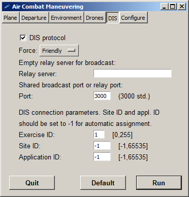
The Force menu allows to choose the force your plane belongs to among Other, Friendly, Opposing and Neutral. By choosing Friendly, drones generated by you will be Opposing using MiG-29 and will attack any other force (including Neutral...). By choosing any other force, drones generated by you will be Friendly using F-16 (and still will continue attacking any craft of any other force...). Your radar and radard warning receiver (RWR) will display as friendly any craft radar emission corresponding to your force, and as hostile any radar emission from other forces.
To play on a LAN in broadcast mode, all the participants must share the exact same subnet mask, for example 255.255.255.0, otherwise the IP broadcast protocol does not work. Participants must also share the same UDP port number (typically 3000) and the same exercise number (in a range from 1 to 255). The Relay server field must be left empty.
To play on a WAN, a relay server is necessary. The ACM package comes with its own relay server program src/dis/server/dis_relay.exe; this relay server must be launched from the command line of some computer having a statically assigned IP address. To start the relay server, type a command like:
dis_relay.exe --port 3000
Other options are available; try with --help. All the participants must then enter the address or the network name of that shared relay server in their Relay server entry field.
Before to explain what to enter in the Site ID and Application ID fields, a note about how the DIS protocol works may help. Every aircraft, missile, cannon burst and, in general, every entity the simulator program generates must have an unique DIS entity ID; this ID is generated combining a sequential counter managed by the program (the entity ID), the application ID (we suggested to use the process number here), and the site ID. But how to assign an unique site ID? ACM addresses this problem by generating a random number and then entering a validation period that last 15 seconds. During the validation period the program listen for incoming packets looking for collisions with already used site IDs. Normally no collision is found, and the program successfully completes the validation and starts sending its packets. Instead, if a collision is detected, a new random site ID is generated and the validation period restarts.
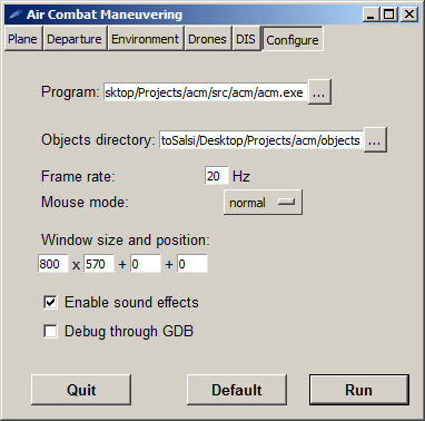
The entry box Program contains the file-name of the ACM executable program, normally located in src/acm/acm.exe. This is the program launched when you press the "Run" button. The acm.tcl launcher invokes that same program to get the list of aircraft models it displays in the Plane panel we explained above, so it is very important to set correctly this path.
The entry box Objects directory contains the directory-name of the directory containing the scenes, the aircraft inventory and other resources the ACM program needs.
The Frame rate is the number of times per seconds the program will update the image on the screen. 20 is probably a good choice for civil aviation, 30 is better in combat.
Mouse movements are translated to ailerons and elevator movements. The Mouse mode menu allows to choose among fast, normal or precise movements. "Fast" may be useful in dog fight combat. "Normal" and "precise" modes are recommended for the normal flight.
Sound effects can be enable and disabled at runtime with CTRL-M.
The remaining options of this panel are quite self-explanatory.
The ACM program can also be started directly from the command line. By default the aircraft model is a C-172 located at latitude zero and longitude zero, which might not be a so interesting place where to start from. So, you may try with another model and some other departure location for which a runway and a scenery is available. Historically, up to the version 5 of ACM the default starting location was the Addison airport at Dallas, Texas, runway 15:
src/acm/acm.exe -plane F-16 -latitude 32-58-40N -longitude 096-50-26W -heading 156
On Windows, the back-slash character \ must be used instead.
The general syntax of the command is
acm [OPTIONS]
where [OPTIONS] is any combination of the following:
-help-version-copyrightDisplays program version, copyright informations and then exit.
-init command-file-nameTake extra command options, in command line format, from the specified text file. For example, say there is a file in your home directory named ‘.acmrc’. Its contents look like this:
-dis-site 34
-dis-appl  4
New lines are treated as normal white space, so feel free to separate command line options onto multiple lines. From a shell, you enter the command:
$ acm -geometry 800x600 -init ~/.acmrc
This would be equivalent to:
$ acm -geometry 800x600 -dis-site 34 -dis-appl 4
-objects path1:path2:...
Scenes, audio effects, aircraft shapes, aircraft data files and other
resources are stored as files inside the objects/ directory.
ACM will look for its data files inside these directories: the current
directory, objects/, ../objects/. So, if you
try to start ACM from outside its base directory, it will complain not to
be able to load these files. This option lets you to specify where these
files actually are. You may specify one or more directories separated
by a colon (Linux) or semicolon (Windows).
-stealthStart ACM in stealth mode. ACM allows users to monitor out-the-window views for any aircraft active in an exercise. Additionally, ACM supports an experimental DIS Request/Grant Control protocol that would permit ACM to “take over” aircraft of similarly enabled applications. See the “Stealth Mode” section for detailed information on this capability.
-subject-entity-id site-id.appl-id.entity-idThis option can be used in conjunction with the -stealth flag
to identify the initial DIS entity to be “stealthed”:
$ acm -stealth -subject-entity-id 32.1.1
-geometry x11-geometry-specification-frame-rate target-frame-rate-hertzSpecifies a not-to-exceed rate at which ACM will attempt to render the cockpit scene. The default is to update the scene as fast as possible, which will use all available CPU time on the system. A good value might be 25 frames per second.
-plane MODELxxx" then look at the error message.
-fuel fuel-lbAllows the user to set the amount of fuel loaded (lb). If left empty, the max amount of fuel allowed by the aircraft is loaded.
-payload payload-lbThe payload = passengers + cargo (lb). The default is 150 lb, a rough estimation of pilot's weight.
-force FORCETells to the DIS protocol to which force you belong among Other (default), Friendly, Opposing or Neutral. Fiendly and Opposing forces are special because the scenery may define a resupply location (that is, your air force base airport) where you may get fuel, munitions and repairs automatically by simply staying still: operations completes within few minutes! These locations are identified respectively as team 1 and team 2 and are read from the departure scenery (see the scenery team record definitions). The force you belongs to also affects how incoming radar beams are displayed (see radar warning receiver) and how drones behave (see drone).
-departure-time TIMEDATEAllows to set the simulated departure date and time. The ISO 8601 date-time format must be used, for example "2017-10-23T12:30". By entering an invalid value, the programs lists all the supported formats along with the error message. The current computer date and time is the default if this option is missing. The state page (SHIFT-E) displays the updated date and time the program is simulating. Sun position and general scene illumination are calculated based on this simulated date and time.
-latitude DD-PP-SS.SSSQ

-longitude DDD-PP-SS.SSSQ

-altitude altitude-msl-feet

-heading initial-magnetic-heading-degrees

-airspeed-kt initial-airspeed-knots
These options may be combined to tailor the startup location of the ACM aircraft. The exact syntax of the latitude and of the longitude is:
degrees[-primes[-seconds]](N|S|E|W)
Seconds and degrees can take a fractional part. Examples:
	-latitude 3.54N -longitude 123-4W

	-latitude 1-2-3.4S -longitude 45-59-22.2E
If the -altitude option is not supplied, ACM automatically
sets the aircraft on the ground at the specified location. Starting airborne
(i.e. specifying an altitude grater that the local terrain altitude) the
initial pitch is set to 2° and the landing gear is retracted. Care should
be taken not to specify an altitude too close to the ground.
By specifying any of these options, the program activates the DIS protocol
and prepares for communicate over the network in multiplayers mode.
It is very important to set properly these values because because each entity generated by the simulator (aircraft, missile or munition) must be univocally identified through its site ID, application ID and a sequential number generated by the program. These 3 numbers form the DIS entity ID that univocally identified each specific entity.
The exercise ID identifies network packets for the specific simulation we want to participate to; the program will simply ignore packets for any other exercise. The allowed range of the exercise ID is from 0 up to 255; the default value is 1.
The site ID identifies your computer and should be unique among
all the participants to the specified exercise. If not specified, or set to -1, a random value is generated and then validated on a period of 15 seconds; if no collisions are detected during this validation period, the randomly generated site ID is confirmed and the program starts sending packets; if a collision is detected, a new random value is generated and the validation period starts again. The allowed range of the site ID is from -1 up to 65535; the default value is -1.
The application ID identifies the specific instance of the ACM program running on a specific site/host. If you are running 2 or more applications on the same host, you may assign them the numbers 1, 2, 3, ... If the special value -1 is assigned, ACM uses the current process number instead. The allowed range of the application ID is from -1 up to 65535; the default value is -1.
-no-sound-visibility flight-visibility-nmSet the clouds/fog density. Runways farther than that are difficult to see or are totally invisible. The default is 50 nautical miles.
-ground-mode MODEAllows to choose th terrain rendering mode among "flat" (default) or "tiled". The flat mode is faster, but the terrain is displayed as a boring uniform color. The tiled mode is slower, but the player may feel some speed and scenery depth feedback.
-clouds-range BASE TOPAllows to set a tick layer of clouds, being BASE the bottom altitude and TOP the top altitude of this layer (ft). The sky is clear if this option is not set or BASE is equal or greater then TOP, which is the default. Clouds are completely opaque to the visible light and to the infrared seekers of the missiles; visibility inside is zero.
-mouse-mode fast|normal|preciseMovements of the mouse are mapped to the corresponding movements of the ailerons and of the elevator. "Fast" uses linear relation, so the aircraft react promptly to the commands but it is difficult to pilot with precision. "Normal" and "precise" are the recommended modes. The default is "normal".
-end-gameThis flag is only valid in stealth mode. Hostile aircraft near the subject aircraft are tracked. If any of these aircraft moves within the subject aircraft’s radar locking range, then ACM will request control of subject aircraft. Control is requested using a variant of the proposed DIS 2.1.4++ transfer control protocol sequence.
-threshold-range threshold-nautical-miles-wind WD/WV-gust GUST_MAX-eye_to_screen_cm CMSets the distance between your eyes and the screen, expressed in cm (1 inch = 2.54 cm). This parameter allows the program to computer the proper scale factor needed to render the outside view without distortions. Default: 50 cm.
-downward_view_angle_deg DEG
Sets the downward view angle (DAV, degrees) below the horizontal axis of
the aircraft. The instruments panel and the engine cover above the pilot,
usually limit its capability to view downward toward the ground, as explained
above describing the acm.tcl program. To
fully display the HUD graphics a DAV of at least 12° is required.
Default: 15°
-drone-mode mode-da FACTOR-hud-modeThe program looks for the following files under any directory specified along with the -objects command line option.
object-map.txt
This file defines a mapping from DIS entity types to 3D object definition files. The object files are used to render an image of the entity.
munition-map.txt
This file defines the explosion and damage producing characteristics of DIS munition entity type and warhead combinations.
inventory
This file defines the performance characteristics of all aircraft types modeled by ACM. The layout of this file is defined in the section titled Defining New Aircraft.
Exit status 0 indicates a normal termination of the program. The specific reason for the termination of the program is sent to standard output; nothing is written if the program terminated by player's request. Some diagnostic message might be sent to standard error, for example invalid DIS packet received or too many entities generated, but these events are not fatal and do not indicate an error in the program.
Exit status 1 indicates a fatal error occurred: internal error, or invalid command line parameters, or system failure in providing some service. Appropriate description of the error occurred is sent to standard error.
General
g Landing gear up/down
b Wheel brakes on/off
h Flaps down 1 step
y Flaps up 1 step
s Deploy speed brakes 1 step (one or more steps, depending on the aircraft model)
w Retract speed brakes 1 step (one or more steps, depending on the aircraft model)
t Start/stop/reset the timer display
z Rudder step left
x Rudder centered
c Rudder step right
l Create a drone opponent aircraft. For Friendly force player, an Opposing drone is created; if the player belongs to any other force, a Friendly drone is created instead. Drones attack crafts belonging to any other force but their own.
d Detach commands from the ACM window, so that you can leave the ACM window in background.
+ Zoom in.
− Zoom out.
Shift-D Displays a state page with several useful informations; among these: current aircraft model; current simulated date and time in ISO 8601 format, zulu time; latitude, longitude and altitude over the WGS-84 ellipsoid; characteristics of the air at the altitude (standard model).
Shift-H Toggle between HUD and "classic instruments".
Shift-M Switch between MH (default) and TH indication (see HUD and HSI sections).
Shift-P Print screen shot to the file
/tmp/acm-dump-*(not available under Windows)Shift-K Calibrate joystick
Shift-$ Play like a drone (toggle).
Ctrl-M Mute/unmute sounds (toggle).
Shift-Q Shift-Q Quit the simulation. NOTE: press two times!
Auto-Pilot System (APS)
Shift-A Engage/disengage the auto-pilot in hold altitude mode or in hold climb rate mode (see The Auto-pilot for details).
Shift-Z Engage/disengage the auto-pilot in hold altitude mode (see The Auto-pilot for details).
Shift-T Engage/disengage the auto-throttle (see The Auto-throttle for details).
Shift-X Engage/disengage the rudder/aileron auto-coordinator (see The Auto-coordinator for details).
Shift-N Engage/disengage the auto-navigator (see The Auto-navigator for details).
Shift-L Engage/disengage the auto-landing (see The Auto-landing for details).
Shift-( Decrease maximum bank angle.
Shift-) Increase maximum bank angle.
Home Release all the auto-pilot sub-systems, with the only exception of the auto-coordinator.
Shift-E Engages/disengages the rate control mode rather than the direct control mode. In direct control mode, the mouse position relative to the center of the window directly sets the position of the ailerons and of the elevator. In rate control mode the mouse position relative to the center of the window sets the roll rate and the pitch rate.
Views
View buttons are located on the PC’s numeric keypad.
KP8 Forward view
KP2 Rear view
KP4 Look Left
KP6 Look Right
KP5 Look Up
KP0 Look Down
n Chase view (this view button is not located on the numeric keypad)
Mouse and Mouse Buttons
Move left/right move ailerons to control the roll left/right
Move forward/backward move elevator to control the pitch.
Left button fire currently selected weapon.
Right button select a weapon.
Joystick Buttons
Button2 (top) Select weapon (Sidewinder IR missile or 20mm cannon)
Button1 (front) Fire selected weapon
Classic instruments
Shift-H Toggle between HUD and "classic instruments".
F7,F8 Adjust altimeter isobaric reference level from 28 to 31 inHg.
F9 "Caging" button: forces alignment of attitude gyro with its case.
F11,F12 Adjust pitch of the symbolic airplane in the attitude indicator.
Radar
r Select radar/HSI/ADF/off mode
Shift-R Toggle between radar modes: Normal, ACM 20x30, STT, Standby. Also Button3 on Microsoft Sidewinder Joysticks.
q Break Lock -- track a different target (also Button4)
Engine control
The meaning of these keys changes when the the auto-throttle is enabled. See The Auto-throttle for details.
1 Engine Idle
2 Decrease Power
3 Increase Power
4 Full Power
a Toggle Afterburner (if available)
SHIFT-! Deploy/retract thrust reverse (if available)
IMPORTANT. The thrust reverse device can be deployed only with engine commanded idle (throttle lever below 25%).
Auto-turn
The auto-turn automatism helps the pilot to keep the desired standard rate of turn of 1.5 or 3.0°/s. Enabling the auto-turn, also the AC is enabled. This is an experimental feature mainly intended for flight test purposes. It might be removed or otherwise changed in future releases of the program.
< (less than) Set left turn rate 3.0°/s
, (comma) Set left turn rate 1.5°/s
> (greater than) Set right turn rate 3.0°/s
. (period) Set right turn rate 1.5°/s
| (vertical bar) Set turn rate 0°/s
/ (slash) Disable auto-turn (see also key Home)
Trim
Trim buttons may be pressed until the desired trim is attainedj Adjust elevator trim to the current pitch command
Ctrl-Shift-UpArrow Forward (down) pitch trim
Ctrl-Shift-DownArrow Aft (up) pitch trim
Ctrl-Shift-LeftArrow Left roll trim
Ctrl-Shift-RightArrow Right roll trim
Home Reset elevator and ailerons trim, disable auto-pilot, auto-throttle, auto-navigator, auto-landing and auto-turn
HSI receiver control
Press r until the HSI gets displayed.
SPACE Switch between NAV1/NAV2/RNAV1/.../RNAV5 receivers.
9,0 Set station frequency
7,8 Set OBS
F3,F4 Set RNAV radial of the WP (only in RNAV mode)
F5,F6 Set RNAV distance of the WP (only in RNAV mode)
ADF receiver control
Press r until the ADF gets displayed.
9,0 Set station frequency
7,8 Move rotatable heading needle
| ACM | Air Combat Maneuvering |
| AAM | Air-to-Air Missile |
| AOA | Angle Of Attack |
| DME | Distance Measurement Equipment |
| DIS | Distributed Interactive Simulation |
| ECM | Electronic Countermeasures |
| HSI | Horizontal Situation Indicator |
| HUD | Head-Up Display |
| IAS | Indicated Airspeed |
| IFR | Instrumental Flight Rules |
| ILS | Instrumental Landing System |
| IR | Infrared |
| KIAS | Knots Indicated Airspeed |
| KT | Nautical Miles per Hour, NM/h. |
| LOC | Localizer |
| MH | Magnetic Heading, the direction referred to the magnetic north pole (see also TH, VAR) |
| NAV | Navigation |
| NDB | Nondirectional Radio Beacon |
| OBS | Omni Bearing Selector |
| RWR | Radar Warning Receiver |
| TAA | Target Aspect Angle |
| TACAN | Tactical Air Navigation System |
| TAS | True Airspeed |
| TEWS | Threat Early Warning System − a form of radar warning receiver also known as radard warning receiver (RWR) |
| RWR | See TEWS |
| TH | True Heading, the direction referred to the geographic north pole (see also MH, VAR) |
| VAR | Magnetic variation, the difference between the geographic north and the magnetic north: VAR = TH - MH. For example, VAR=+6=6°E means that the local magnetic north points toward 6° geographic. |
| VFR | Visual Flight Rules |
| VOR | VHF Omnidirectional Radio Range |
| WP | Waypoint |
Numbers are indicated with 4 significant digits.
| Name | Symbol | Value(1) | Equivalences |
|---|---|---|---|
| Time | |||
| Second | s | ||
| Minute | min | 60 s | |
| Hour | h | 3600 s | |
| Length | |||
| Meter | m | 3.281 ft = 0.0005400 NM | |
| Foot | ft | 0.3048 m = 0.0001646 NM | |
| Nautical Mile(2) | NM | 1853 m = 1.853 Km = 6076 ft | |
| Speed | |||
| Knot | KT | 1 NM/h | 0.5144 m/s = 1.853 Km/h |
| Feet per minute | fpm | 1 ft/min | 0.3048 m/min = 0.005080 m/s |
| Mass | |||
| Pounds | lb | 0.4536 kg | |
| Kilogram | kg | 2.205 lb | |
| Slug | slug | 1 lbf / (1 ft/s2) | 32.17 lb = 14.59 Kg |
| Acceleration | |||
| Earth acceleration at sea level(3) |
g | 9.806 m/s2 = 32.17 ft/s2 | |
| Force | |||
| Newton | N | 1 kg m / s2 | 0.1020 Kgf = 0.2248 lbf |
| Kilogram-force(4) | Kgf | 1 kg g | 9.806 N = 2.205 lbf |
| Pound-force(4) | lbf | 1 lb g | 4.448 N = 0.4536 Kgf |
| Slug-force(4) | slugf | slug g | 143.1 N = 32.17 lbf |
1. A value is given only for those units that are defined in terms of other base units.
2. Nautical miles are a practical length unit used in naval and aerial navigation, as its value is is very close to the length of a arc-minute measured along a meridian, or the length of a arc-minute measured along the equatorial line.
3. As Isaac Newton explained, on the Earth at sea level every body fall under its weight with the same acceleration, here indicated with the slanted letter g, not to be confused with the gram unit of mass "g".
4. The weight is the force with which the Earth attracts bodies toward its center. So it is useful for practical calculations to associate to every mass unit (kg, lb, ...) its corresponding weight-force unit whose symbol is the same as the mass unit with "f" added. Then, for example, 1 lbf is the weight of 1 lb mass measured on the Earth at sea level.