
The WGS-84 geodetic ellipsoid. In this figure, P=[x,0,z].
by Riley Rainey
updated by Umberto Salsi
Geodetic coordinates and the WGS-84 ellipsoid
Defining new zones
Defining new scenes
Defining new aircraft
Frame and aerodynamicsDefining new objects
Engine
Landing gear
Armament
IEEE 1278.1 (DIS) compliance
Suggested further reading
The WGS-84 defines a reference shape for the Earth which is very close to the real shape of our planet; the concepts of local vertical, local horizontal plane, altitude and longitude are all referred to this ideal shape named geodetic ellipsoid. The figure below illustrates the right-handed Cartesian reference centered on the geodetic ellipsoid:
The surface of this ellipsoid are the solutions of the equation x2/a2 + y2/a2 + z2/b2 = 1 where "a" is the length of the major semi-axis (or equatorial semi-axis) and "b" is the length of the minor semi-axis (or polar semi-axis):
a = 6378137.0000 m
b = 6356752.3142 m
These values, although very close to the real size of the Earth, are by definition of the WGS-84 model. Although very accurate measurements of the Earth are available and the actual shape of the Earth, named geoid, is known with very high precision, such an accuracy does not make much difference in most practical applications and can be ignored. So in general any measurement of latitude, longitude and altitude, if not otherwise stated, is to be intended as geodetic, that is refereed to the WGS-84 ellipsoid.
The north pole is located at Cartesian coordinates [0,0,b] and the south pole is located at [0,0,-b]. The rightmost point [a,0,0] has latitude zero and longitude zero; the Greenwich meridian crosses this point joining the two poles.
For any point P=[x,y,z] in the Cartesian reference, a corresponding mapping to the geographic coordinates [lat,lon,alt] has to be defined. First, the local vertical is the line crossing P and perpendicular to the surface of the ellipsoid in its point A; the tangent plane to this point is the local horizontal plane at altitude zero. The local vertical line is the local plumb line. Note that the vertical line in this model, just like on our real planet, does not cross the center of the ellipsoid but intersects the x axis at some point B.
The latitude is defined as the angle between the local vertical and the xy plane. Calculating this latitude given the Cartesian coordinates is not simple; curious may look at the module src/dis/dis/earth in the sources of ACM. Latitudes range from 90S at the south pole, up to 90N at the north pole. The 0N latitude (or 0S if you prefer) is the equator.
The longitude is defined as the angle between the point P and the xz plane measured around the z axis: lon=atan(y/x). No surprises here. Longitudes range from 180 degrees west up to 180 degrees east; obviously the 180W meridian coincides with the 180E meridian. The 0E meridian (or 0W if you prefer) is named Greenwich meridian.
The mean sea level (MSL) is the surface of the ellipsoid; altitudes are measured as distance of the point P from the local horizon beneath it. All altitudes under ACM are intended referred to this MSL.
The local terrain altitude (measured vs. the MSL, of course) varies from point to point. ACM looks at the altitude of the nearest runway within 100 NM to determine the terrain altitude; if none found, it assumes zero. Negative altitudes are also possible.
A zone is a range of longitude and latitude bound to the scenery file where the items inside the zone are listed. Sceneries are dynamically loaded and un-loaded by the program as necessary as the plane moves around the globe.
As the program starts and initializes, it looks for a zones file named zones.txt normally located under the objects/ directory. The zones files lists all the zones that are available to the program along with the range of geodetic coordinates the scene covers, for example:
# zones.txt file:
35N  40N  125W  120W  zones/usa/sfrancisco.txt
30N  35N  120W  115W  zones/usa/losangeles.txt
35N  40N  120W  115W  zones/usa/lasvegaswest.txt
#35N  40N  115W  110W  zones/usa/lasvegaseast.txt
30N  35N  115W  110W  zones/usa/tucson.txt
30N  35N  100W  095W  zones/usa/dallas.txt
40N  45N  075W  070W  zones/usa/newyork.txt
35N  47N  006E  019E  zones/europe/italy.txt
30N  35N  040E  045E  zones/middleeast/iraq.txt
The Italy scenery file has been compiled by hand. The Iraq only contains some sample runways and it is otherwise incomplete. All the USA sceneries have been generated automatically from the FAA data base using the the program available under tools/faaairports; further zones covering the USA territory can be added in the same way.
The image below summarizes the currently defines zones, but other might be added in future release and others can be added by the player itself:
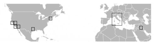
As the simulated aircraft flies, any zone within 200 NM from the aircraft is loaded and made available to the simulation, so runways, radio stations and features therein defined enter the simulation: runways can be seen, radio stations can be tuned, etc. Zones left behind or too far away are un-loaded from memory.
The zones file is a simple text file organized by lines, each line representing a zone with 5 fields:
Latitude and longitudes can be indicated in several ways, here are some examples:
10N     10-20-30.400S     30.500S
10E     10-20-30.400W     30.500W
Fields must be separated by at least one white space. Apart from that, white spaces are ignored. Empty lines and lines beginning with '#' are ignored.
Notes and restrictions
Note that for extended items, some of their points may lie outside the zone. For example, although the center of the runway must be in, one or both of its ends can be out; the locator of the ILS must be in, but the corresponding glide slope antenna can be out.
Note that the maximum latitude is 90N, the north pole; if a zone extends up to this limit, its upper edge is a point. Due to the rules above, the north pole does not belong to the zone, and there is no way to put an item at that exact location; this does not seem to be a severe limitation, though.
Don't try to fly over the poles! There is a know bug in the program that prevents to fly over the poles. Near to these locations (below 1 NM), the computation of the aircraft's next step fails and the aircraft tilts unpredictably, mostly crashing -- look at the comments in the src/dis/dis/earth for more.
There is no limit to the number of zones that can be defined. If each zone covers a 5x5 DEG range of latitude and longitude, considering only the range of latitudes [80S,80N], and since 70% of the Earth is covered by water, one may expect the maximum number of zone that might be needed to cover all the globe be about 692.
The scene file defines the contents of a zone. It should be stored as a ASCII text file. Every record occupies exactly one line, with leading and trailing spaces ignored. Fields in a record are separated by one or more spaces or tabulation characters. Empty lines and lines beginning with the character '#' are ignored.
Friendly and Opposing DIS participants may have a resupply base where to get fuel, munitions a repairs. Servicing starts as the aircraft stops close enough to the specified location. Typically, these location will be positioned and oriented at the end of a runway at the player's air force base airport. Example:
Fields:# Friendly air force base: TEAM1_LOC 32-58-18.798N 096-50-16.604W 0 0 # Opposing air force base: TEAM2_LOC 33-58-00.000N 097-50-00.000W 0 0
0 Type: TEAM1_LOC, TEAM2_LOC
1 Latitude
2 Longitude
3 Initial Altitude MSL (ft) (this value ignored)
4 Initial Heading (degrees, true) (this value ignored)
An X11-style #RRGGBB color specification defining
the color of the ground. Red, green and blue color components are
hexadecimal value from 00 to FF. Example:
GROUND_COLOR #305030
Fields:
0 Type: GROUND_COLOR
1 Color
The record entry of the ACM scene describing a runway can take two forms, depending on the available informations: the old one (RWY) and the new one (RWY2). The RWY format requires the geographic coordinates of both the ends of the runway. The RWY2 requires only the center of the runway and its true heading. The syntax of the runway identifier (field no. 2) must be of the form:
H[S]/H[S]
where H is the heading (an integral number between 1 and 36) and S is a capital letter ("L", "C" or "R"). The S part of the identifier is optional. A leading "0" in an identifier is allowed. The runway identifiers can be specified in any order.
Example of the RWY record format:
RWY ADS 15/33 644 7202 100 32-58-40.245N 096-50-25.820W 32-57-33.383N 096-49-56.608W
Fields of the RWY record:
0 Record Identifier: RWYExample of the RWY2 record format (same runway):
1 Three/Four letter airport code
2 Runway identifier
3 Runway Altitude (ft, MSL)
4 Runway Length (ft)
5 Runway Width (ft)
6 Near End Latitude
7 Near End Longitude
8 Reciprocal End Latitude
9 Reciprocal End Longitude
RWY2 ADS 15/33 644 7202 100 32-58-06.81N 096-50-11.21W 160.0
Fields of the RWY2 record:
0 Record Identifier: RWY2
1 Three/Four letter airport code
2 Runway identifier
3 Runway Altitude of the Center (ft, MSL)
4 Runway Length (ft)
5 Runway Width (ft)
6 Latitude of the Center
7 Longitude of the Center
8 Runway geographical heading (DEG)
The model of the terrain simulated by ACM is very simple and efficient: the elevation of the nearest runway gives the local terrain altitude, the distance being calculated relatively to the center of the runway. Nevertheless, this behavior has a strange implication: between two runways at different altitudes there is a step line where the local altitude suddenly change. Crossing this step line taxing on the ground, the aircraft would crash its landing gear.
In the figure below the terrain to the left side of the step line has elevation 500 feet, while the terrain in the other side has elevation 510 feet. Unfortunately in this case we have a problem, since the step line crosses both the runways.
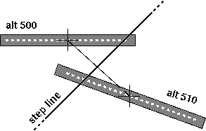
The problem of the step line crossing the runways.
The only practical solution to this problem is to keep all the runways of a given airport at the same exact altitude.
A "NAV" record may be a VOR, a DME or a NDB. The TACAN stations of the ACM world behave simply as VOR/DME stations. VOR and ILS stations frequency ranges from 108.00 MHz up to 117.95 MHz.
OMARKER, MMARKER and IMARKER are just like NDB stations but with limited range (20 NM rather than 100 NM). NDB station frequency ranges from 200 KHz up to 529 KHz. This latter upper limit is a rather arbitrary value set in ACM, but most of the stations do not exceed 415 KHz.
Example:Fields:NAV TTT VOR/DME 32-52-08.98N 097-02-25.81W 540 113.10 - NAV FWH TACAN 32-46-17.46N 097-26-22.07W 663 108.7 024X NAV RBD NDB 32-40-36.98N 096-52-15.91W 670 287 -
0 Record Identifier: NAV
1 Up to four letters identifier
2 NAVAID Type: VOR, DME, VOR/DME, VORTAC (=VOR+DME), TACAN (=VOR+DME), NDB, OMARKER (=NDB), MMARKER (=NDB), IMARKER (=NDB)
3 Transmitter Latitude
4 Transmitter Longitude
5 Transmitter Altitude (ft, MSL)
6 VHF Frequency (MHz for VOR/DME/ILS stations and KHz for NDB)
7 TACAN channel number, or '-' if not available. Ignored by ACM anyway.
An ILS (instrumental landing system) is a LOCALIZER antenna (emitting the signal giving the right heading toward the runway) that may include also a glide slope antenna (GS, giving the deviation from the glide plane) and a DME antenna.
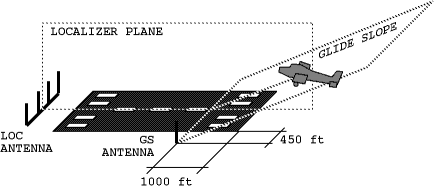
Typical ILS arrangement around the runway.
In the real world, each antenna has its latitude, longitude and elevation, but under ACM the simplified ILS record does not allow to specify the location of the DME antenna and provides only one elevation field whose value is shared among the LOCALIZER, the GS and the DME antenna; the distance displayed by ACM actually is the distance from the LOCALIZER. The recommended workaround is to indicate the elevation of the GS antenna to allow precise landing at the expected distance from the threshold; if not available, the elevation of the DME antenna should be indicated for closer match between displayed distance and the expected value; finally, the elevation of the LOCALIZER antenna can be indicated. Limitations and recommendations are detailed below.
The LOCALIZER antenna is normally located near the reciprocal end of the runway and the signal is normally aligned with the centerline of the runway. The exceptions are the LDA and SDF antennas which may deviate from the centerline of the runway or even be completely unrelated with any runway at all.
The GS antenna, when available, is normally located near the side of the runway threshold. The elevation of this antenna is critical in order to land at the specified spot on the runway, so its value should be indicated when available.
The DME antenna, when available, is always assumed to be coincident with the LOCALIZER antenna; there is no way to specify another location, so the distance displayed in the program may differ from the official navigation charts.
| Type | Description |
|---|---|
|
LOCALIZER LDA SDF |
LOCALIZER antenna only available. LDA and SDF are handled just like a LOCALIZER, the only difference is that the chart generator program is advised a corresponding runway end may not be available for this ILS and so no error should be emitted. The elevation field should be set with the elevation of the locator antenna. |
|
ILS LOC/GS |
LOCALIZER and GS antennas both available. The elevation field should specify the elevation of the GS antenna, when available. |
|
LOC/DME LDA/DME SDF/DME |
LOCALIZER and DME antennas both available. LDA and SDF are handled just like a LOCALIZER, the only difference is that the chart generator program is advised a corresponding runway end may not be available for this ILS and so no error should be emitted. The elevation field should specify the elevation of the DME antenna, when available, or the elevation of the LOCALIZER otherwise. |
| ILS/DME | LOCALIZER, GS and DME antennas available. The elevation field should specify the elevation of the GS antenna when available, or the elevation of the DME or of the LOCALIZER (in this order of preference). |
Example:
ILS 30 ILS IAIW 108.9 34-18-47.161N 097-01-38.280W 34-17-59.533N
097-00-35.018W 729.2 4.92 315.5 3.00
Fields:
0 Record Identifier: 'ILS'
1 Runway Identifier:
2 ILS Type: see table above
3 Four letter Identifier
4 VHF Frequency (MHz)
5 Localizer Transmitter Latitude
6 Localizer Transmitter Longitude
7 Glide Slope Transmitter Latitude ('-' for Localizer-only approaches)
8 Glide Slope Transmitter Longitude ('-' for Localizer-only approaches)
9 Glide slope antenna elevation when available, or localizer antenna elevation (ft, MSL)
10 Localizer beam width (DEG)
11 Localizer geographic bearing (DEG)
12 Glide slope angle (DEG) ('-' for Localizer-only approaches)
FEATURE features/tower.obv 32-58-04.800N 096-50-16.800W 644 0
Fields:
0 Record identifier: FEATURE
1 Object filename, either absolute or relative to the scene file
2 Latitude
3 Longitude
4 Altitude (ft, MSL)
5 Orientation angle (degrees, true)
The ACM program loads all the aircraft models defined in the aircraft.txt file; this file is searched in all the the specified object directories. Lines beginning with # are ignored by the program and can be used to add comments.
The inventory file may contain several include and aircraft records. The include record has syntax
include "some/other/file"
and allows to include the content of other inventory files in a more structured way. The path can be relative to the current inventory file. The aircraft record is described below in detail.
The stout-of-heart may be interested in creating new aircraft types. Some
of this information must be generated by hand, but I did create a program
to help me generate aircraft objects: GEDIT. GEDIT is a rudimentary
Motif program that allows you to create 3-dimensional objects. It is
available in the directory gedit of the distributed package.
The syntax of the aircraft record is not complex. The program doesn't complain about missing numeric values, and they are assumed to be zero.
# Aircraft Inventory for ACM 5.0
# See ACM-Bibliography for further information about the sources of this
# information.
# MiG-29 Fulcrum
# MiG-29M information was derived from two sources: [Spick87] and [AirI Aug92].

aircraft "MiG-29" {
    Description "Mikoyan-Guryevich MiG-29M Fulcrum"
    Object "mig29.obj"
The visual description of an ACM aircraft is stored separately in V-library format and specified in the Object field. The name of the file may include a relative path which is resolved against the directory of the current file. This file describes a set of polygons that roughly approximates the shape of the actual aircraft. I used GEDIT to create most of the ACM aircraft objects. If not available, you may leave this parameter commented-out, but chase view will not be available and you craft will be invisible to the other players...
    WingArea     400.0     # (wingS) Wing surface area (ft2)
    WingHalfSpan 18.87     # (wings) Wing half-span (ft)
    WingHeight    0.0      # (wingh) Height of the wing aerodynamic center
                           #    above the CM (ft)
    Chord        9.61      # (c) Mean geometric chord of wing (ft)
    AspectRatio  3.56      # (aspectRatio) aspect ratio
    EmptyWeight  22500.0   # (emptyWeight) Empty mass (lb)
These values are usually quoted with an aircraft's performance figures.
The WingHeight is used to estimate the ground effect, and
its value is positive for wings above the center of mass.
    # Max. wing load (lb):
    MaxLoadZPositive    273000  # 10*(EmptyWeight+50%*MaxFuel) (+10 g)
    MaxLoadZNegative    137000  # 5*(EmptyWeight+50%*MaxFuel) (-5 g)
The maximum vertical load, either climbing (MaxLoadZPositive)
or diving (MaxLoadZNegative). If the weight the wings have
to sustain is greater than that, the structure suddenly breaks and the
aircraft gets destroyed.
For civil aircraft you may guess these values as 2.5*MTOW and 1.0*MTOW. Military aircraft, and fighters expecially, are reported to sustain up to some number N of positive "g" and some other number Q of negative "g". If not indicated, you should suppose at least 60% of the fuel contributing to the mass:
MaxLoadZPositive = N * (EmptyWeight + 60%*MaxFuel)
MaxLoadZNegative = Q * (EmptyWeight + 60%*MaxFuel)
where typical values for N range from 7 to 10, and Q=3.
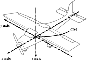
The reference frame of the aircraft, with main inertial axes
and center of mass (CM) indicated.
    # (I(x,y,z)) Moments of inertia (lb ft2)
    Ixx 10000
    Iyy 75000
    Izz 80000
These are hard values to simple guess. I have grabbed values where they were available and simply guessed sometimes, too. Moments of inertia in an actual aircraft are not constant. Most notably, as an aircraft burns fuel, it's weight distribution, center-of-gravity, and moments of inertia change. In ACM, however, moments of inertia and CM do not change.
    # (cFlap) Lift due to flaps (yields Clift of 1.0 at max extension)
    CFlap 0.64279
    BetaStall     15.0    # (deg) Stall angle for rudder
    CFlapDrag     0.0467  # (cFlapDrag) Drag due to Flaps
    CGearDrag     0.03    # (cGearDrag) Drag due to Gear
    CSpeedBrake   0.03    # (cSpeedBrake) Drag due to Speed Brake
                          # at 90 degrees


    # (CDb) Drag Characteristic equation [Wave+body]
    # independent variable is mach number

    CDb {                 # (CDb) Drag Characteristic equation [Wave+body]
        # independent variable is mach number
        0.0, 0.020,
        0.2, 0.020,
        0.95, 0.015,
        1.05, 0.045,
        2.00, 0.030,
        10.0, 0.030
    }
In ACM, wave/body drag coefficient is a function of the airspeed expressed
as a Mach number. Less drag makes for a faster aircraft. This function
generally has a maximum near Mach 1.0. You probably should not change
this table unless you really know what you're doing.
For the CFlap coefficient see below.
    CLift {               # (CLift) Lift-slope curve (vs alpha)
        -3.0, 0.0,
        -1.05, 0.0,
        -0.576, -2.199,
        -0.556, -2.23,
        -0.524, -2.199,
        0.524, 2.199,
        0.556, 2.23,
        0.576, 2.199,
        1.05, 0.0,
        2.0, 0.0
    }
In ACM, the coefficient of lift is purely a function of angle of attack (alpha) and of the speed. The CLift table gives the coefficient of lift for some values of the AoA "alpha". In the example above, the maximum coefficient of lift is 2.23 at 0.556 RAD = 32 DEG of AoA. Above this angle, the lift drops abruptly and the plane stalls. The coefficient of lift also depends on the current flap deflection angle according to the function:
CL = CLift(alpha) + sin(flaps) * CFlap
being CLift(alpha) the interpolated value given by the CLift table above. The total lift force is given by the equation:
L = 1/2 r WingArea V2 CL
where r is the air density (r=1.225 Kg/m3 at sea level), V is the airspeed and CL is the coefficient of lift.
    CnBeta { # (CnBeta) Yaw moment due to sideslip equation
        0, -0.08125,
        0.523540, -0.078125,
        0.785340, -0.0609375,
        1.047198, 0.125,
        1.58, 0.0
    }
In ACM negative yaw due to sideslip means that the aircraft is "weathercock stable", that is, the aircraft tends to yaw in a way that reduces the sideslip component.
    ClBeta { # (ClBeta) Roll moment due to sideslip equation
        0, -0.0125,
        0.43633, -0.015,
        0.78540, 0.125,
        1.58, 0.0,
        3.142, 0.125,
    }
A negative value means that the aircraft will roll in the opposite direction of the sideslip component, tending to make the aircraft more stable.
    CDBOrigin   0       # (CDBOrigin, CDBFactor) Drag due to sideslip
    CDBFactor   0.5
    CDBPhase    0       # (CDBPhase) sideslip drag phase (deg)
CYBeta -0.85 # (CYbeta) Side-force from side-slip [dCY/dBeta]
CYBeta is the "lift" due to sideslip. This is the factor that allows to roll 90 degrees from level, kick the rudder a lot, and still stay level. Not all simulators take this into account.
    EffElevator   0.60 # (effElevator) Elevator effectiveness
    CmAlpha      -0.30 # (cmSlope) CmAlpha curve slope
    EffRudder     0.35 # (effRudder) Rudder effectiveness
    MaxRudder     20   # (maxRudder) max Rudder (deg)
    MaxAileron    20   # (maxAileron) max Aileron (deg)
    MaxFlap       20   # (maxFlap) max flap setting (deg)

    # (flapRate) flap extension rate (about 2 secs to fully extend flaps)
    FlapRate      10   # (deg/s)

    MaxSpeedBrake 80   # (maxSpeedBrake) max Speed Brake setting (deg)

    # (speedBrakeRate) rate of speed brake extension (2 secs to full ext)
    SpeedBrakeRate 40  # (deg/s)

    # (speedBrakeIncr) speed Brake increment per keystroke
    SpeedBrakeIncr 80  # (deg)
These values determine the characteristics of the aircraft's speed brakes (speed brakes are used in the air, wheel brakes are used on the ground). MaxSpeedBrake determines the maximum extension of the speed brake panels. SpeedBrakeIncr determines how far one press of the s key will increase the speed brake extension. It does not need to be an even increment of MaxSpeedBrake. SpeedBrakeRate determines how fast the brakes will deploy or retract.
    Clda  0.048 # (Clda) roll moment from aileron offset
    Cldr  0.004 # (Cldr) roll moment from rudder offset
    Clp   -0.27 # (Clp) roll damping
    Cmq   -8.0  # (Cmq) pitch damping factor
    Cnr   -2.0  # (Cnr) yaw damping factor
These factors characterize some of the roll, pitch and yaw characteristics of the aircraft. They are in the NACA form. Damping factors determine how quickly an aircraft returns to a steady state after some change in control input. Larger negative damping factors make for a more stable aircraft.
    # Speed limits at MTOW. Leave undefined or set to 0 if unknown.
    MTOW  32250.0    # maximum takeoff weight (lb)
    #Vs0     42.0    # stall speed, full flaps (kt)
    #Vs1     50.0    # stall speed, no flaps (kt)
    #Vfe    100.0    # max speed with flaps extended (kt)
    #Vno    145.0    # normal operation speed (kt)
    #Vne    164.0    # never exceed speed (kt)
These parameters allow the program to set or calculate several speed limits (IAS). These speed limits are used to draw the colored arcs on the air speed indicator. Every arc is displayed only if its start and end are known, and it is now drawn otherwise. These speed limits are also considered to simulate structural failures when exceeded, as detailed below. Leave commented-out or set to 0 the parameters that are unknown: the program will try to guess the missing values of simply will left them undefined if this guess is not possible.
MTOW is the maximum take off weight (lb).
Vs0 is the stall speed at MTOW, full flaps, at sea level. It is indicated by the beginning of the white arc in the anemometer. If undefined or set to zero, the program tries to calculate this value with the following formula:
Vs0 = sqrt( 2 MTOW earth_g / (r WingArea CL) )where:
earth_g is the gravity acceleration at sea level.
r is the air density at sea level.
CL is the lift coefficient calculated with:
CL = maxCLift + CFlap sin(MaxFlap)
being maxCLift the maximum coefficient of lift as given by the CLift curve.
Vs1 is the stall speed at MTOW, without flaps, at sea level. It is indicated by the end of the short white arc in the anemometer. If undefined or set to zero, the program calculates this value with the following formula:
Vs1 = sqrt( 2 MTOW earth_g / (r WingArea maxCLift) )
Vfe is the maximum speed with flaps extended. It is indicated by the end of the longer white arc in the anemometer. Exceeding this speed with flaps deployed, also partially, causes a flaps failure that makes them unusable. If undefined or set to 0, the Vfe is unlimited.
Vno is the normal operation speed, that is the maximum speed in turbolent air conditions. It is indicated by the beginning of the yellow arc in the anemometer. Flying above this speed in turbulent air, a vertical wind gust of 30 ft/s would cause a vertical positive or negative acceleration above the maximum structural load capacity of the wings. If undefined or set to 0, the Vno is estimated with the following formula:
Vno = 2 earth_g (MaxLoadZNegative + EmptyWeight) / (r WingArea * b * MAX_GUST)where:
b = 6.302 is the slope of the CLift curve in its linear range; this value was actually calculated for the C-172RG but it is also very close to that of the other aircraft models, so it is assumed as constant.
MAX_GUST = 30 ft/s is the conventional maximum vertical wind gust intensity assumed as reference to calculate Vno.
Vne is the speed that must never be exceeded. It is indicated by a short red line. Flying above this speed limit the aircraft may suffer a catastrophic structural failure. If undefined or set to zero, this limit does not apply.
    # (viewPoint) pilot's viewing location
    ViewPoint { 14.75, 0, -5.375 }
This is the location of the pilot's eye view outside of the cockpit.
    # (tailExtent) as we rotate, this part may drag
    TailExtent { -18.165, 0.0, 1.191 }
This defines where the aft-most lower part of the aircraft is located. This is the part of the aircraft that may scrape the ground as we rotate. This value is not currently used. Instead we simply limit up-pitch on the ground to 20 degrees.
    EngineType "GenericJetEngine"

    MaxFuel  9750  # (maxFuel) maximum internal fuel (lb)

    # engine lag factor (how fast does it respond to throttle changes
    EngineLag -3.0

    # Engine data based on updated RD-33K engines cited in [AirI Aug89].
    # (maxThrust) max static thrust, military power (lbf)
    MaxThrust 27000

    # (maxABThrust) max static thrust, afterburner on (lbf)
    MaxABThrust 44000

    HasThrustReverser 0 # 0=no (default), 1=yes
This section describes the engine and its performances. One among these types of engine can be chosen:
Maximum static military and afterburner thrust values can usually be
found in documents that describe aircraft performance.
Setting MaxABThrust to the same value of MaxThrust
disable the AB for those aircraft that lack this device.
For the conversions, remember that 1 pound = 1 lb g = 4.448 N = 0.4536 Kgf.
The HasThrustReverser parameter tells if the aircraft has a thrust
reverse device. Set to 1 if available or 0 if not. If this parameter is missing
the default is "no". With thrust reverse deployed and engine at the max power,
the resulting reverse thrust is calculated as 50% of the max forward thrust.
    Thrust {        # (Thrust) Mach Number vs. thrust
        0,   1,
        1.7, 1.5,
        2.0, 0.84,
        5,   0.5
    }

    ABThrust {      # (ABThrust) afterburner thrust table
        0,   1,
        0.5, 1,
        1,   1.21,
        1.7, 1.7,
        5,   1.64
    }
The Thrust and ABThrust corrects the static thrust value for the
aircraft's Mach number. Unless you have hard information about this,
leave these fields alone. The ABThrust table is ignored when
the AB device is disabled.
    # (spFuelConsump) specific fuel consump(lb fuel/lb T x hr)
    SpFuelConsump    0.68

    # (spABFuelConsump) AB specific fuel consump(lb fuel/lb T x hr)
    SpABFuelConsump  2.55
These fields define the specific fuel consumption (fuel consumed per pound of thrust per hour).
    # Landing Gear control parameters
    GearRate   30   # (gearRate) gear extension rate from 0 to 90 DEG (DEG/s)
    MuStatic   0.08 # (muStatic) static coeff of friction no-brakes
    MuKinetic  0.05 # (muKinetic) moving coeff of friction no-brakes
    MuBStatic  0.7  # (muBStatic) static brakes-on
    MuBKinetic 0.6  # (muBKinetic) moving brakes-on
These four values characterize the amount of friction that the wheels generate when in contact with the ground. If F is the force (usually a weight) that load a wheel, then F*MuStatic is the friction force when the wheel is at rest; F*MuKinetic when the wheel is rolling. MuBStatic and MuBKinetic have the same meaning with the only difference that the brakes are on. The maximum theoretical value of any of these is 1.0.
NOTE 1. In our landing gear, only the main gear wheel have the brakes; the nose wheel can't brake.
NOTE 2. The MuKinetic and MuBKinetic are probably misnomers as
these coefficients are more commonly known as "MuRolling" instead. Proper
"kinetic" coefficients are involved when the wheel skids over the runway,
either longitudinally (blocked brakes) or laterally. In ACM brakes
never block, but still wheels can skid laterally over the runway. The
coefficient involved in the skidding behavior is currently hard-coded
in the gear.c module. Moreover, the gear breaks when the
lateral force applied to the wheel exceeds the empty weight
of the aircraft. This limit too is hard-coded into the source program.
MaxNWDef 72 # (maxNWDef) maximum nosewheel deflection (deg)
The MaxNWDef is the max deflection of the nose wheel, so that
the radius of turn of the aircraft is R=Q/sin(MaxNWDef) where
Q is the distance between the nose gear and the middle point
between the wheels of the main gear (see the figure below).
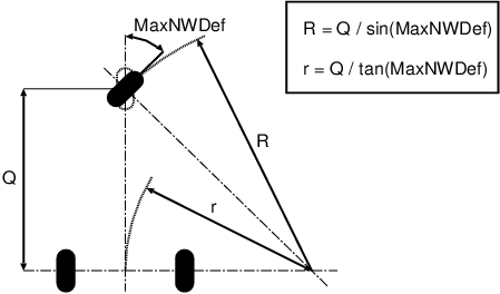
Radius of turn on the ground.
    # (rm) location of right main gear attachments {x,y,z} (ft)
    Rm { -2.2, 4, 1.702 }

    # (rn) location of nose gear attachments {x,y,z} (ft)
    Rn { 9.395000, 0, 1.807 }

    Km    18220.7 # main oleo spring factor (lbf/ft)
    Kn    4278.34 # nose oleo spring factor (lbf/ft)
    Dm    10000   # main oleo damping factor (lbf s/ft)
    Dn    80      # nose oleo damping factor (lbf s/ft)
    Gm    1.5     # main strut length with tire (ft)
    Gn    1.5     # nose strut length with tire (ft)
    CmMax 1.0     # (cmMax) main max oleo extension distance (ft)
    CnMax 1.5     # (cnMax) nose max oleo extension distance (ft)
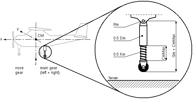
Parameters of the landing gear.
The parameters Rn and Rm give the positions of the
nose and main gear attachments, while Gn and Gm
are their total length including the tire but excluding the oleo extension
CnMax and CmMax. As a first approximation of these
parameters, you can take these values (all the distances are measured in feet,
1 ft = 0.3048 m):
Rn.x- Attachment point of the nose landing gear strut, x coordinate (ft). Positive for tricycle landing gear, negative for bicycle landing gear.
Rn.y- Always zero.
Rn.z- Attachment point of the nose landing gear strut, z coordinate (ft).
CnMax- The oleo + spring part of the nose gear extends from zero up to this length (ft).
Gn- Length of the rigid part of the nose landing gear strut (ft). The total length of the nose gear strut including tire is then this value plus the current extension of the oleo part.
Rm.x- Attachment point of the right main landing gear strut, x coordinate (ft). Negative for tricycle landing gear, positive for bicycle landing gear.
Rm.y- Attachment point of the right main landing gear strut, y coordinate (ft). Always positive; the left main gear it is assumed to be at -Rm.y but with the same Rm.x and Rm.z components of the right main gear.
Rm.z- Attachment point of the right main landing gear, z coordinate (ft).
CmMax- The oleo + spring part of each main gear strut extends from zero up to this length (ft). About half foot for light planes, and up to 1.5 feet for larger ones.
Gm- Length of the rigid part of the each main landing gear strut (ft). The total length of each main gear strut including tire is then this value plus the current extension of the oleo part.
Every wheel of the landing gear is attached to the aircraft through a spring (K) and a damper (D). The parameters referring to the main landing gear are the sum for the left and right gear, so the actual parameter for each wheel strut is half the value reported in the inventory (see the picture above).
The landing gear parameters are difficult to estimate. We will give some simple rule to set good starting values based on reasonable assumptions.
Km- Total spring factor for the left+right main landing gear (lbf/ft), then each spring is half this value. The main landing gear must sustain most of the weight of the aircraft, so a reasonable rule is to set this spring (left + right) so that the strut be half compressed with the aircraft in its empty weight:
Km = 2 * EmptyWeight / CmMax
For example, if the empty weight is 10000 lbf and the strut maximum extension is 1.5 ft, we have Km = 13300 lbf/ft.
Kn- Nose spring factor (lbf/ft). The nose spring must sustain the static weight that depends on its distance from the CM. Moreover, on bicycle landing gears the nose must sustain also the braking. Here to we will assume the oleo damper be half compressed while the aircraft is braking at its empty weight. The resulting quite complex formula is:
Kn = 2 * EmptyWeight * (-Rm.x / (Rn.x - Rm.x) + MuBKinetic * (Rm.z + Gm + CmMax)/Rn.x) / CnMax
Note that the distances that appear in this formula have their sign, so usually Rm.x is negative while Rn.x is positive. For bicycle landing gear we can neglect the braking effect by assuming MuBKinetic=0 in the formula above, but consider that these aircraft usually have an higher static pitch for which this simple formula is not valid anymore.
Dm- Total damping factor for the left + right landing gear strut (lbf s/ft). The principal role of the damping factor in the main gear is to adsorb harder landings at high descending speed, when the spring cannot help because is still not compressed at all. 600 fpm is usually the maximum allowed vertical speed for which aircraft are tested. That means that the force produced by the damper when the wheels of the main gear hits the ground is F=Dm*600 fpm. Since in ACM there is an hard-coded vertical limit to the main gear equal to 1.5 times the empty weight for each leg of the main landing gear, the following formula gives a safe value for Dm:
Dm <= 0.2 * EmptyWeight
For example, if the empty weight is 10000 lbf, then the damping factor should not exceed 2000 lbf s/ft.
Dn- Damping factor for the nose landing gear strut (lbf s/ft). A good starting value might be Dm calculated above.
The program GEDIT can be used to determine correct landing gear
locations. I then use the program tools/balance.c to generate
the appropriate values for the spring factors for each new aircraft type that
I create. Note that neither GEDIT nor balance.c currently
calculate oleo damping factors.
Choosing the right values for the landing gear is difficult, and the program may terminate abruptly with one of the following messages related to the landing gear:
StructurePoints 15 # (structurePts) maximum structural damage
This value characterizes how much damage can be absorbed by the aircraft before it starts falling to the ground (drones simply explode). A detailed description of the meaning of this field is available as a comment to the objects/munition-map.txt file, where all the recognized warheads are listed along with their effectiveness.
    # Radar data based on N-019 Pulse Doppler radar cited in [AirI Aug89].
    RadarOutput   15000 # (radarOutput) radar output (watts)
    RadarTRange   38    # (radarTRange) tracking radar range (NM)
    RadarDRange   55    # (radarDRange) detection radar range (NM)
    TEWSThreshold 0     # Radar Warning Receiver threshold (watts)
If you have any information about the radar capabilities of the aircraft, here's the place for them. The detection range is the maximum range that a target can be seen on radar. No attempt is made to take into account the radar cross section of the target. The tracking range is the range required to get a lock onto the target.
    # Weapons
    WeaponCount 9
Number of weapon hard-points. The following fields are ignored if this value is set to zero, so they can be omitted if the aircraft does not carry weapons at all.
    HardPoint0 { 7.0, -4.0, 0.0 }
    HardPoint1 { 0.357, 15.6, 0.0 }
    HardPoint2 { 0.357, -15.6, 0.0 }
    HardPoint3 { 1.5, 9.0, 2.0 }
    HardPoint4 { 1.5, -9.0, 2.0 }
    HardPoint5 { 1.5, 8.0, 1.5 }
    HardPoint6 { 1.5, -8.0, 1.5 }
    HardPoint7 { 1.5, 10.0, 1.5 }
    HardPoint8 { 1.5, -10.0, 1.5 }
These are the XYZ locations relative to the aircraft CM of each weapon. By defining these, each missile or cannon fires from its appropriate location on the aircraft.
    WeaponStation   0 "M61A1"   500 0   0
    WeaponStation   1 "AIM-9M"   0   0   0
    WeaponStation   2 "AIM-9M"   0   0   0
    WeaponStation   3 "AIM-9M"   0   0   0
    WeaponStation   4 "AIM-9M"   0   0   0
    WeaponStation   5 "AIM-9M"   0   0   0
    WeaponStation   6 "AIM-9M"   0   0   0
    WeaponStation   7 "AIM-120"  0   0   0
    WeaponStation   8 "AIM-120"  0   0   0
}
The WeaponStation directive defines the type of weapon located at
each hard point. The first argument is the number of the hard point, that
ranges from 0 up to WeaponCount−1. The second argument is
the name of the weapon. Then three integer numbers follow whose meaning depends
on the specific weapon. The table below summarizes by examples all the
available weapons:
| Example | Notes |
|---|---|
WeaponStation 0 "M61A1" 500 0 0 |
M-61A1 "Vulcan" cannon. 500 is the number of rounds initially supplied to the cannon. The other two numbers are ignored. |
WeaponStation 1 "AIM9M" 0 0 0 |
AIM9M "Sidewinder", infra-red guided, short range, air-to-air missile. The other 3 numbers are ignored. |
WeaponStation 2 "AIM120" 0 0 0 |
AIM-120 "AMRAAM", radar guided, medium-range, air-to-air missile. The other 3 numbers are ignored. |
WeaponStation 6 "MK82" 0 0 0 |
Mark 82 250 lb standard drop bomb. The other 3 numbers are ignored. |
Remote aircraft may submit detonation PDUs claiming you have been hit by something. The objects/munition-map.txt lists all the recognized munitions by their DIS entity type, along with their effectiveness.
An "object" can be the shape of an aircraft (field "Object" of the aircraft inventory file) or a feature of the scene file (record "FEATURE"). The format of the object file, described here, is copied from the ACM Flight Simulator Frequently-Asked Questions List maintained by Brad Bass (bass@convex.com).
The first line is the object name.
The 2nd line has two integers which represent the number of points and the number of polygons in the object.
Then, the points are listed, one per line, with the point id number followed by the X, Y and Z coordinate (North, East, Down). The units are feet.
Finally, the polygons are listed as color, number of corners, and the list of point id numbers. The color may be expressed as a single color or as a front and back color. Also, the polygon can be flagged as "one-sided" -- that is visible only from the front.
For example:
pyramid                  # the object name
5 4                      # the point count and polygon count
1 28000 0 0              # the
2 0 16000 0              #   points that
3 -35000 0 0             #     describe
4 0 -14000 0             #       the
5 0 0 -8200              #         corners
#788b63      3  1 2 5    # side 1 - color (X-style), cornercount,
                         #   corner list
violet       3  2 3 5    # side 2
(blue red)   3  3 4 5    # side 3 - front is blue, back is red
(green clip) 3  4 1 5    # side 4 - one-sided polygon
ACM emits and recognizes the following DIS PDU Types:
Entity State
Fire
Detonation
Electromagnetic Emission
The ACM program may simulate several entities, including the aircraft the user is flying on, each missile it fires and possibly other entities. For each entity it simulates, the program sends a state packet to all the other participants every 4.8 seconds along with the dead reckoning algorithm each remote program must apply in the meanwhile. The program also sends an updated state packet when it detects the actual state of the entity deviates from the stated dead reckoning method for more than a given amount.
The following dead reckoning methods are recognized:
| Name | DIS enumeration | Description |
|---|---|---|
| Other | 0 | NOT SUPPORTED. |
| Static | 1 | Entity does not move. |
| FPW | 2 | Entity moves at constant speed. |
| RPW | 3 | Entity moves at constant speed and rotates at constant speed. |
| RVW | 4 | Entity moves at constant acceleration and rotates at constant speed. |
| FVW | 5 | Entity moves at constant acceleration and does not rotate. |
| FPB | 6 | NOT SUPPORTED. |
| RPB | 7 | NOT SUPPORTED. |
| RVB | 8 | NOT SUPPORTED. |
| FVB | 9 | NOT SUPPORTED. |
| RPW | 10 | NOT SUPPORTED. |
| RVW | 11 | NOT SUPPORTED. |
For methods not supported, the state is not updated and the remote entity looks moving by steps.
Entities managed by ACM emit entity state PDU’s specifying the RPW(3) dead reckoning method. No articulation parameters are currently sent by entities managed by ACM. As with most current DIS-based simulations, altitudes are expressed as heights above the WGS-84 ellipsoid, not as heights above the geoid. Dead reckoning threshold values are hard-coded in the src/acm/manifest.h file:
| Description | Value |
|---|---|
| Maximum time between Entity State PDUs | 4.8 seconds |
| Dead Reckoning Cartesian distance error | 3 meters |
| Dead Reckoning angular orientation error | 2 degrees |
When operating in IEEE 1278 mode, the default UDP port number for PDU transmission is 3000.
ACM supports an experimental DIS 2.1.4++ control request protocol. It permits it to “take over” aircraft of similarly enabled applications. For ACM to take over an aircraft, it must have model information in the “inventory” file describing the characteristics of that aircraft type. Those aircraft entities will be marked with an asterisk (*) in the left margin of the stealth browser display. Double click an aircraft entity id to take control.
|
Field Size (bits) |
Transfer Control Request PDU fields | |
|---|---|---|
| 96 | PDU Header |
Protocol Version—8-bit enumeration |
|
Exercise ID—8-bit unsigned integer |
||
|
PDU Type —8-bit unsigned integer Protocol Family—8-bit enumeration Timestamp—32-bit unsigned integer Length—16-bit unsigned integer |
||
|
Padding—16-bits unused |
||
| 48 | Originating Entity ID |
Site—16-bit unsigned integer |
|
Application—16-bit unsigned integer |
||
|
Entity—16-bit unsigned integer |
||
| 48 | Receiving Entity ID | Site—16-bit unsigned integer |
|
Application—16-bit unsigned integer Entity—16-bit unsigned integer |
||
| 32 | Request ID | 32-bit unsigned integer |
| 8 | Required Reliability Service | 8-bit enumeration |
| 8 | Transfer Type | 8-bit enumeration |
| 48 | Entity ID to be Transferred | Site—16-bit unsigned integer |
|
Application—16-bit unsigned integer Entity—16-bit unsigned integer |
||
| 32 | Number of Record Sets (R) | 32-bit unsigned integer |
|
96 + (L1 x Q1) + P1 |
Record Set #1 | Datum ID—32-bit enumeration |
|
Record Set Serial Number—32-bit unsigned integer |
||
|
Record Length—16-bit unsigned integer (L1) |
||
|
Record Count—16-bit unsigned integer (Q1) |
||
|
Record Values—(L1 x Q1) bits |
||
|
Padding—P1 bits |
||
|
· · · |
||
|
96 + (LR x QR) + PR |
Record Set #R |
Datum ID—32-bit enumeration |
|
Record Set Serial Number—32-bit unsigned integer |
||
|
Record Length—16-bit unsigned integer (LR) |
||
|
Record Count—16-bit unsigned integer (QR) |
||
|
Record Values—(LR x QR) bits |
||
|
Padding—PR bits |
||
Total Transfer Control Request PDU size:
320 + Sumi=1..R(96 + (Li x Qi) + Pi) bits
where R is the number of Record Sets.
ACM currently ignores record sets in a transfer control PDU.
This section specifies the 8-bit enumeration for the Transfer Type field of the Transfer Control PDU.
| Field Value | Nature |
|---|---|
| 0 | Other |
| 1 | Controlling application requests transfer of an entity |
| 2 | Application desiring control requests transfer of an entity |
| 3 | Mutual exchange / swap of an entity |
| 4 | Controlling application requests transfer of an environmental process |
| 5 | Application desiring controls request transfer of an environmental process |
| 6 | Mutual exchange of an environmental |
Assuming Ownership
Accepting Ownership by Request
Another feature of ACM’s transfer control protocol support is that other applications may request that ACM take control of an aircraft that the other application controls.
...and the source code of ACM which contains lots of interesting comments!