The magnetic compass.
by Riley Rainey
updated by Umberto Salsi
Tutorial
Take-offThe Magnetic Compass
Landing
The Classic Instruments Panel
The Head-Up Display
The HSI
The ADF
The Auto Pilot System
The Auto-pilotLights Panel
The Auto-throttle
The Auto-coordinator
The Auto-navigator
The Auto-landing
The Auto-turn
The Radar System
Electronic Countermeasures
Weapon Systems
Drones
Stealth Mode
Start the launcher program acm.tcl. The first thing to do is checking the whole program be properly configured. Open the Configure panel and make sure the executable program and the objects directory be set. Set a frame rate of 20 Hz, mouse mode normal, window size of 700 x 500. It may need to exit the launcher (press the the Quit button) and start it again in order to see the list of the available planes in the You panel.
In the You panel choose the Cessna 172 retractable gear C-172 with about 200 lb of fuel and 200 lb of payload (your body).
In the Instruments panel choose "Classic instruments", 50 cm of eye distance from the screen, 10 degrees of downward view angle.
In the Scene panel choose the Dallas scene from the objects directory.
In the DIS panel disable the DIS protocol.
Press the Run button to start the actual ACM program. Your mouse is the control stick. The neutral position is the center of the window. Moving the mouse away from you pitches the plane down, moving it back pitches the plane up. Left and right inputs roll the aircraft in the corresponding direction and turn the nose wheel.
Press F9 to cage the attitude indicator: this will speed-up the alignment process that would take several minutes otherwise.
Hint. Controlling the aircraft is much simpler by enabling the rate control mode (press SHIFT-E).
Press the full throttle key (the "4" key on the main keyboard, NOT the numeric keypad!). Keep the mouse in the neutral position until you are moving at about 55 KT, then gently pull the mouse about two-thirds of the way down the view window. You should pitch up and lift off the ground fairly easily. Maintain a pitch angle between 7 and 10 degrees by gently moving the mouse and leave your airspeed build.
When the vertical speed indicator indicates a stable positive climb rate (500 fpm or so), you may retract the landing gear by pressing the "g" key. Level the plane at a safe altitude of about 2000 ft and throttle down to about 80% of the engine RPM (use the "2" and "3" keys of the main keyboard, NOT those of the numeric keypad).
Hint. Move the mouse very gently around the center of the window, looking at the attitude indicator for changes. For normal level flight you should keep about +3 degrees of pitch and zero bank angle.
Congratulation, you successfully made your first take-off!
We are still flying the C-172 and now it's time to land. Set engine RPM to about 70% (keys "2" and "3") and deploy the landing gear by pressing the "g" key. Reduce the pitch and try to keep the airspeed at 75 kt and the descending rate at -400 fpm. Keep wings level. In this our first attempt we will land randomly somewhere on the green field and will not attempt to actually land on a runway.
Rule. The normal glide slope for landing should be around -3 degrees. In order to keep a glide slope near to this value, the descent speed should be about 5 times the airspeed. For example, if the airspeed is 100 kt, then the descent rate should be around 5 x 100 = 500 fpm.
Look at the radar altimeter. When it indicates 50 ft from ground it's time to start the flare maneuver by reducing the sink rate to about -200 fpm or less, trying to touch the ground as gently as you can. But do not hesitate to much because the speed decreases very rapidly and you risk to stall! As the radar altimeter indicates zero, put the engine to idle power (key "1") and gently lower the nose gear. Leave the plane to slow down, or press "b" to engage the brakes.
Congratulation, you successfully made your first landing!
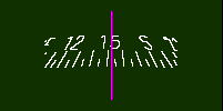
The upper-right corner of the window displays the magnetic compass, simulated by the program mostly for didactical purposes. The compass card contains the magnets and it is mounted on a small pivot point located above its center of mass. This allows the compass card to rotate freely and to float as a pendulum by a maximum of +/−18° in pitch and roll following the direction of the apparent vertical line. Above this angular limit the compass hits violently the side of the casing and its indication becomes unreliable for some time.
The magnetic compass.
The magnetic compass does not simply indicate the magnetic heading (MH) of the aircraft, but instead it moves and rotates under the dynamic and magnetic effects. By definition, the magnetic north is the direction of the magnetic field vector projected over the local horizontal plane. That's why the magnetic compass card has to be as close as possible to the horizontal plane in order to align its magnets with the horizontal component of the magnetic field.
When the aircraft is at rest on the runway, or it is flying in straight, level flight at constant speed, the compass card is perfectly parallel to the horizon and it rotates until it is perfectly aligned with the horizontal component of the Earth magnetic field. On the contrary, when the aircraft is turning or otherwise accelerating, the compass card deviates from the expected MH even more than 30 degrees under the effect of the vertical component of the magnetic field. The compass cards displayed by the others instruments (HSI, ADF and HUD) are feed by the flux gate sensor and each stabilized by its own gyroscope. The MH indicated by these instruments does not suffer from the the deviations of the magnetic compass.
In case of instruments failure, turns based on the magnetic compass have to be timed, because the magnetic compass cannot provide a valid reference for the final heading. For example, starting from MH=east and having to rotate at MH=north, the pilot shall perform a timed standard left turn at 3°/s for exactly 30 seconds.
The magnetic field on the Earth is calculated using the World Magnetic Model library from NOAA (https://www.ngdc.noaa.gov/geomag/WMM/soft.shtml) and it is used to display the current magnetic heading of the aircraft, to rotate the magnetic compass, and to calculate the magnetic bearing at each VOR station. The file of the coefficients objects/WMM.COF provided along the package is valid for dates in the range from year 2015 up to year 2019 included; beyond this range, a warning is displayed and a new updated file coefficients should be installed.
It is important to note that the components of the Earth's magnetic field are calculated respect to the current year and day, so updated navigation charts may be needed. The navigation charts provided along this package are outdated, so magnetic bearings there indicated may differ more or less from the calculated values.
Press Shift-H to alternate between the HUD and the classic instruments panel. The classic instruments panel mimics the instrumental equipment of a typical light aircraft, as the Cessna 172-RG. The program does not simply reproduce the same informations already shown by the HUD, but it tries to emulate also errors and limitations introduced by these instruments and that make the job of the pilot harder (and then, more interesting for us). In the following we will describe each instrument and its properties. The interested reader should refer to the aeronautical literature for more informations about their proper usage.
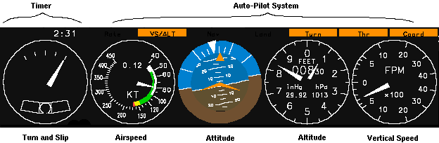
Instruments of the classic panel.
In the classic instrument mode the HSI and ADF always indicate the MH, as the compass card of these instruments is driven by the flux gate sensor. In the HUD mode, on the contrary, the HSI and ADF are driven by the inertial platform and are able to indicate both TH and MH.
The pointer moves indicating the rate of turn around the vertical axis of the aircraft. Normally the aircraft z axis is very close to the geodetic vertical, so that the indicated value is nearly equal to the actual yaw rate. At high roll angles or high bank angles, this is not strictly true and small differences between the actual yaw rate and the indicated value may arise.
The central mark of the turn indicator indicates zero turn rate, while the other marks indicates 1.5°/s and 3°/s turn to the left or to the right.
Below the turn rate indicator there is a curved glass containing a little ball. This ball moves from the central position under the action of a lateral acceleration, typically as a consequence of an uncoordinated turn.
It indicates IAS on a non-linear scale (kt). This value is calculated using the formula below:
IAS = TAS * sqrt(rho/rho0) * (1 + 1/8*(1 - delta)*M^2)
being TAS the true airspeed along the x axis, rho is the air density at the current altitude, rho0 the air density at sea level, delta is the ratio P/P0 between the current air pressure and the pressure at sea level, and M is the Mach number.
The digital number indicates the Mach number in the range 0.00 - 9.99.
Also known as artificial horizon, it provides to the pilot the pitch and the bank angles. Inside this instrument there is a gyro whose axis is parallel to the local apparent vertical direction.
An erection system (slowly) forces the axis to follow this vertical, but this alignment process can take some time, typically from 2 to 5 minutes, depending on the amplitude of the misalignment. Accelerations produced by speed changes (takeoff) and prolonged turns can misalign the gyro. To prevent that misalignment, the erection system gets disabled if the measured acceleration differs from the expected "g" value +/-2%. That it means, for example, that turning with angles of bank greater than 12° will not disturb the alignment.
The gyro can follow the aircraft movements up to +/-70° angles of bank and pitch. Above this limit the gyro will hit the internal lock, tumbling abruptly and loosing its alignment. For this reason the pilots has also a "cage" knob (F9) that forces the alignment of the gyro with its case, speeding-up the following fine alignment performed by the erection system. The "cage" knob is also useful to fast align the gyro at the start of the program.
The orientation of the gyro is represented to the pilot as a ball. Over this ball are drawn the horizon line and several pitch marks separated by 5° up to +/-30°. The stylized figure of a little aircraft's wings can be moved up and down by the pilot (F11, F12) so that it becomes aligned with the line of the horizon. This adjustment should be performed in level flight at constant speed so to indicate zero pitch. Once so adjusted, the indicated pitch will match the angle of climb as indicated by the flight path marker of the HUD, provided that these maneuvers are performed at the same airspeed at which that adjustments was made.
A triangle indicates the angle of bank, at steps of 10, 20, 30, 60 and 90 degrees. This triangle moves in the opposite direction of the horizon, so to indicate the actual direction of the turn.
This instruments indicates the altitude. The digital display shows the flight level (bigger digits) followed by the two less significant digits of the current altitude. The pointer indicated tens feet. Since in ACM the atmospheric conditions are always stable and equal to the standard atmosphere, the indicated altitude is also the actual altitude above the sea level (MSL).
By default the altimeter indicates the standard pressure altitude (29.92 inHg) but you can change the isobaric level of reference pressing F7 and F8.
For negative altitudes, the instrument passes from 0 to 99990 ft, then 99980 ft and so on.
It indicates the rate of change of the altitude from −4000 ft/min up to +4000 ft/min. This instrument has a lag of about 3 seconds, so it takes some time before it stabilizes to the actual vertical speed. Changes in altitude should then be made with the aid of the attitude indicator: first, move the aircraft to the expected pitch, then look at the VSI for fine adjustment of the desired vertical speed rate.
Flying with the classic instruments panel may be challenging at first because there is some delay between pilot's input and the actual feedback from the instruments. Things get simpler if you accurately plan every maneuver before starting any action. The two rules below should help:
Bank rule. To attain the standard rate of turn of 3°/s in a coordinated turn, first calculate the required angle of bank as given by this approximated formula:
bank = 0.15 * airspeed
For example, at 100 kt the angle of bank is 15°. You can calculate easily this value taking the airspeed, dropping the last digit and then adding half of its value. Then roll-in at this angle of bank looking at the attitude indicator: once the aircraft starts to turn, adjust the rate looking at the turn indicator.
Pitch rule. At constant airspeed, changes in vertical speed are related to changes in pitch angle by this approximated formula:
vertical_speed_change = 2 * pitch_change * airspeed
For example, flying at 100 kt, every degree of pitch change will result in a change of about 200 fpm of vertical speed. Use the pitch scale of the attitude indicator to move the aircraft's nose to the expected pitch angle. Then, some seconds later, the VSI will indicate the actual vertical speed so achieved allowing to fine-tuning the pitch.
The Head-Up Display (HUD) is a collection of indicators that permits pilots to focus their attention on what's going on outside of the cockpit. These indicators are projected onto a flat pane of glass located near the windscreen. Much of the information is displayed graphically to give the pilot a quicker understanding of the immediate situation.
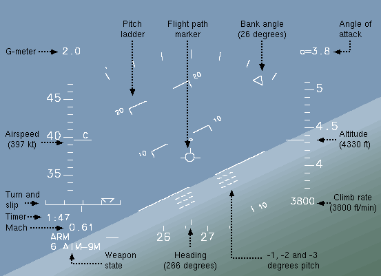
The Heads-Up Display.
Four tape-style "ladders" display basic flight information. On the left, is the aircraft true airspeed (TAS). Each minor tick on the airspeed ladder represents 10 nautical miles per hour (also known as knots and abbreviated "kt").
On the right is the altitude over the sea level (MSL). Each tick represents 100 feet. A rate-of-climb readout is located just below this ladder; rate-of-climb is expressed in feet per minute.
In the lower center is a horizontal heading ladder. Each tick represents five degrees.
In the center is an attitude ladder. Each line corresponds to ten degrees of aircraft pitch. The ladder rolls as the aircraft does, providing an artificial horizon.
The compass displays the the true heading (TH, default) or the magnetic heading (MH). Press Shift-M to switch between the two modes. The HSI displays the mode currently selected. Implementation note: the local magnetic variation is that of the nearest NAVAID station or ILS station.
The
ACM HUD has two indicators to give the pilot cues as to the planes
current angle of attack and sideslip. First, above the altitude
ladder, is a readout of the plane's current angle of attack in
degrees. The ACM F-16 will stall at a positive angle of 30 degrees
and a negative angle of -30 degrees.
Additionally,
a plane-shaped "flight path marker" indicates the
aircraft's current direction of travel. Level flight occurs when the
flight path marker is aligned with the zero- degree artificial
horizon line.
A readout of the current vertical G-force on the pilot is located above the airspeed ladder.
Below the throttle indicator are discretes that show the state of the currently selected weapon system.
The turn and slip indicator.
The turn and slip indicator displays the yaw rate and the lateral acceleration. The triangle indicates the standard rates of turn of 1.5°/s and 3°/s. The vertical bar indicates the lateral acceleration, every tick being 0.25 g. The left part of the figure above illustrates a left turn at 3°/s with about 0.4 g of lateral acceleration (uncoordinated turn). The right part of the figure illustrates a coordinated turn without lateral acceleration. Coordinated turns are obtained combining ailerons and rudder.
The Mach number is the ratio between the airspeed and the speed of the sound at the current altitude. The table below shows the speed of the sound at some typical altitudes:
| Altitude (ft) | Speed of the sound (kt) |
|---|---|
| 0 | 659 |
| 10000 | 640 |
| 20000 | 615 |
| 30000 | 590 |
The Mach number appears only when the speed is at least 0.20 Mach at the current altitude.
At low altitude, below 2500 ft over the terrain, the radar altimeter scale is displayed. The radar altimeter shows the distance in hundreds of feet between the terrain and the wheels of the main gear.
The Horizontal Situation Indicator, or HSI, is a nifty device to aid in instrument flying. It receives and displays VOR/DME stations and ILS stations. The compass card of the instrument gets automatically oriented toward the magnetic north. A sensor of the earth magnetic field (also known as flux gate) detects the orientation of the magnetic north. A gyroscope provides short term stability while the aircraft is maneuvering and, when in level flight, the flux gate provides the correction to the gyroscope drift. The result is an instrument that provides highly accurate aircraft heading in both turning and straight flight, without a requirement for the pilot to manually adjust for drift as in a standard directional gyro.
NOTE. Instruments mounted on the real aircraft have both the slave mode (as described here) and the free mode. When the pilot selects this latter mode, the flux gate gets disabled (for example because a failure) and the HSI operates simply as a directional gyro that needs to be manually aligned with the magnetic compass.
In ACM the HSI system occupies two slots of the instrument panel: the left slot is the control panel and the right slot is the HSI display. The HSI panel receives radio signals from VOR, DME, LOCATOR and GS stations, it elaborates all these informations and then it feed the HSI display.
To save space on the screen, these two panels share the same area with the ADF receiver and the radar system. Use the r key to change radar/ADF modes until the HSI is displayed.
The HSI control panel. It displays several informations. Mode can be NAV1, NAV2, RNAV1, ..., RNAV5. These modes will be described below in separated paragraph. There are two independent NAV1 and NAV2 receivers and five RNAV calculators. Use the SPACE to switch between NAV and RNAV modes.
FRQ is the frequency of the station, as selected by pilot (9, 0).
Once the station has been selected and properly tuned, the receiver starts listening for the signal emitted from the station that can provide also its name displayed in STA (station name).
If the station provides also a distance measurement equipment (DME) this distance gets displayed.
The RAD and DST fields are meaningful only in RNAV mode and are described in the respective paragraph.
The HSI display. In the TH mode (the default, as shown in the figures below) the indicated north is the geographic north. In the MH mode (Shift-M) the indicated north is the magnetic north. The TH mode is mainly useful for estimated navigation based on geographic charts, since these maps are always oriented toward the geographic north pole. The MH mode is the preferred mode for aeronautical navigation, since all the angular indications (VOR, ILS and runways headings) are always referred to the local magnetic north.
The curse deviation indicator (the purple segment at the center of the display) gets displayed only if the corresponding radio signal is correctly received. The slope deviation indicator (the purple arrow to the right of the display) gets displayed only if the corresponding signal is correctly received.
Use the 7 and 8 keys to orient the Omni Bearing Selector (OBS). The OBS displays the digital value of the selected direction.
In NAV mode the HSI displays the VOR/DME bearing, angular deviation (CDI) from the selected radial (OBS) and distance DME.
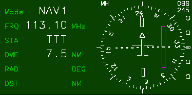
The HSI tuned on a VOR/DME station in NAV mode.
Having two NAV receivers is very useful, both for navigation and to approach the runway. For example, we can tune NAV1 on the VOR station we are leaving and NAV2 on the station we are going to. Or, we can tune NAV1 on the terminal-VOR of the airport, and NAV2 on the ILS station.
The frequency of a VOR station ranges from 108.x0 MHz up to 111.x5 MHz with x being an even digit 0, 2, 4, 6, 8 for terminal VOR, and from 112.00 MHz to 117.95 MHz for en-route VOR.
The signal range of a terminal VOR is about 40 NM, and the range of an en-route VOR is about 200 NM due to the limited power emitted by these stations. Moreover, electromagnetic signals at hight frequency (100 MHz and more, as those emitted from VOR stations are) propagates in a direct line of sight. Because of the curvature of the Earth, the range at which the signal can be received may be even more limited depending on the current altitude of the aircraft:
range = K * (sqrt(station_altitude) + sqrt(aircraft_altitude))
where the altitudes are expressed in feet and the resulting distance in NM. The value of the constant K in the formula above is K=1.064 as you can easily prove with simple geometrical considerations assuming the Earth to be a sphere of radius R=3438 NM. Then, for example, if the altitude of the station is 500 ft and the altitude of the aircraft is 4000 ft, the signal cannot be received beyond the distance of 91 NM.
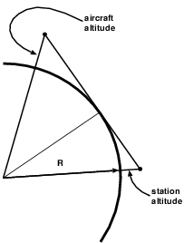
| The Earth is round and radio signals at high frequency (100+ MHz) propagate in stright line. |
Every dot of the CDI scale indicates a deviation of 1.7° from the selected radial. For stations providing a DME, the distance from the selected radial is given by this simple formula:
distance_from_radial = distance_from_DME / 100 * 3 * CDI
For example, if the distance from the DME station is 20.0 NM and the CDI indicates 2 dots, then the distance from the selected radial is 20/100*3*2=1.2 NM.
In NAV mode, also ILS stations can be tuned.
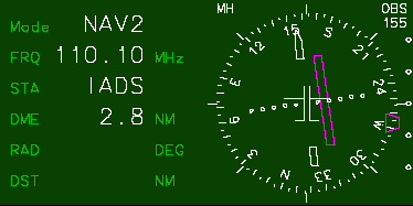
The HSI tuned on a ILS station.
The frequency of ILS stations ranges from 108.x0 MHz up to 111.x5 MHz, with x being an odd digit 1, 3, 5, 7, 9.
An ILS station can be received up to the distance of about 18 NM and in a range of +/-50° from its bearing angle.
Every dot of the CDI scale indicates a deviation of 0.4° from the LOCATOR plane (not the deviation from the OBS, but the pilot can still select an OBS for its own reference). Every tick of the glide slope scale indicates a deviation of 1° from the glide path angle of the ILS station (typically 3°).
The RNAV calculator can store up to 5 waypoints (WP). The pilot enters the WP in the RNAV calculator in polar coordinates (radial RAD and distance DST) referred to some VOR/DME station, along the frequency of the VOR/DME station itself.
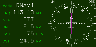
The HSI tuned on a VOR/DME station in RNAV mode.
The waypoint is set at radial 75, distance 24.5 NM from the VOR/DME.
NOTE: bare VOR stations and ILS stations cannot be tuned in RNAV mode.
Once the control panel has been set, the RNAV calculator feeds the HSI display with angular deviation and distance from the selected waypoint (WP). Then the pilot can fly toward the WP just like if it were a "phantom" VOR/DME station. The DME field of the control panel displays the distance from the WP (not the distance from the VOR/DME station used as a reference).
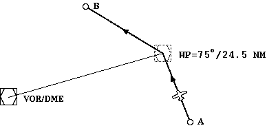
A "phantom" VOR/DME guides the aircraft along the route from A to WP and then from WP to B.
Press the r several times until the ADF receiver gets displayed. The compass card of this instrument is automatically aligned with the magnetic north tanks to the signal provided by the flux gate, and stabilized with a gyroscope.
The ADF occupies two slots of the instrument panel: the left slot is the ADF panel were the frequency and the ID of the NDB station gets displayed; the right slot is the ADF display that shows the magnetic bearing of the NDB station.
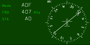
The ADF control panel (left) and bearing indicator (right).
Tune the desired station pressing 9 and 0.
In the real world the range of the NDB signal depends on many factors. In ACM this range is set to 100 NM for navigation NDB stations, and 20 NM for instrumental approach stations (OMARKER, MMARKER, IMARKER).
The auto-pilot system (APS) consists of several functional blocks, each one taking control of some flight parameter. The relations between blocks are indicated in the diagram below. Every block can be engaged or disengaged by the pilot independently from the others blocks, with the only exception of AW and AP that might be required by AN and AL.
In a emergency, the APS can be disabled pressing the key Home.
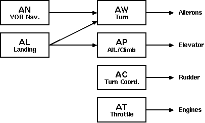
Block diagram of the Auto Pilot System (APS).
A note about the terminology: "APS" is the whole system of auto-piloting, while the "AP" is the sub-block that control the altitude or the climb rate. Perhaps the AP should had been split in two independent blocks performing "hold altitude" and "hold climb rate", so resolving the ambiguity. This can be a change left to the future releases of the program.
The auto-pilot (AP) helps the pilot keeping a given rate of climb or a given altitude. When engaged, the AP adds a correction term to the current elevator control that can grow up to the 50% of the full elevator control range:
elevator_setting = pilot_setting + AP_correction_term
Even when the AP is engaged, the pilot preserve the ability to control the aircraft, while the AP will try to do its best to keep constant the controlled parameter. Press Shift-A to engage/disengage the AP. When engaged, the "AUTOPILOT" word is displayed on the HUD.
Engaging the AP to hold the rate of climb. Once the desired rate of climb has been attained, engage the AP. The AP will grab the current rate of climb and will use this value as a reference to calculate the elevator correction. The rate of climb must be greater than +100 ft/min or less that −100 ft/min.
Engaging the AP to hold the altitude. Once the desired altitude has been attained, engage the AP. The AP will capture the current altitude and will use this value as a reference to calculate the elevator correction. The rate of climb must be near to zero +/− 100 ft/min. As an alternative, press Shift-Z: in this case the AP grabs the current altitude and keeps this value as reference.
Disengaging the AP. Press Shift-A or Shift-Z. The elevator correction term will be released smoothly within 3 seconds, restoring the full control of the elevator.
AP alarm. When the AP correction grow beyond the 25% of the full elevator control range, the "AUTOPILOT" displayed in the HUD (or the "Pilot" light in classic instruments mode) will blink. In this case the intervention of the pilot is required. Adjust the pitch or the engine power until the alarm disappear.
AP limitations:
- max vertical acceleration: +/- 0.1 g
- hold altitude mode, max vertical speed: +100 fpm
- hold altitude mode, min vertical speed: -1000 fpm
- disengaging the AP, smooth release of the elevator within 3 s
The auto-throttle (AT) controls the engine thrust in order to hold a given IAS limiting the acceleration to the range -0.5g .. +0.1g. When the selected TAS cannot be attained, the pilot is warned by the blinking "ATxxx" in the HUD (or the blinking light "Thr" in classic instruments mode).
The AT can be engaged/disengaged pressing Shift-T. When enabled, the current TAS is grabbed and used by the AT as the target speed. The value of the current target speed is displayed in the HUD to the right of the speed scale. For example, the indication "AT120" means that the target TAS is 120 kt.
When the AT is enabled, the buttons that normally control the engine change their meaning as follow:
1 disable the AT device and sets the minimum thrust (20% RPM).2 decrease the target TAS by 5 kt.
3 increase the target TAS by 5 kt.
4 disable the AT device and the AP and sets the maximum thrust (100% RPM).
Press Shift-T again to disengage the AT keeping the current throttle setting.
Controlling the rudder through the keyboard and without a physical feedback of the lateral acceleration is really difficult, so often compromising the precision of the maneuver on coordinated standard turns.
The auto-coordinator (AC) feature allows the rudder to be controlled by the program in order to cancel the lateral acceleration, indicated by the slip indicator. The AC can be enabled/disabled pressing Shift-X. Once enabled, a little "AC" gets displayed to the side of the slip indicator (or the "Coord" light in classic instruments mode) and all the turns are automatically coordinated.
A good way to do a standard turn in AC mode is bringing the aircraft to the expected bank angle, then checking the turn rate indicator for the expected turn rate. The figure below plots the expected bank angle vs. the current true air speed for 1.5°/s and 3.0°/s standard rates of turn.
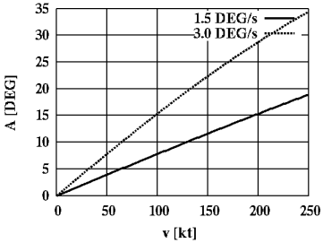
Bank angle versus TAS.
The arrows keys are very useful to do little heading corrections in AC mode, for example to align the aircraft to the runway. Larger turns can be done simply moving the mouse.
The keys z c that control the rudder are still enabled, but not really effective. You may use them for even finer heading corrections.
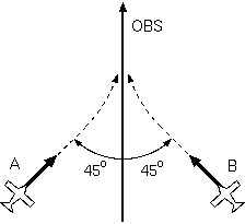
The auto-navigator (AN) allows to follow the radial indicated by the OBS set into the HSI panel. Once enabled, the AN automatically compute a proper approaching route bringing to the radial, then it maintain this radial. Ailerons and rudder are controlled in order to correct the magnetic heading of the aircraft according to an algorithm explained below.
Enabling the AN. To enable the AN follow these steps:
 The approaching path.
The AN computes the path bringing to the chosen radial. Normally
an approaching angle of OBS+45° gets chosen if the aircraft is located
to the left of the radial (point A of the figure) otherwise an heading of
OBS−45° gets chosen (point B of the figure). The aircraft then turns
toward the heading so computed, either clockwise
or counter-clockwise depending on the current heading. For example, if
the target heading is 360° (north) and the aircraft is currently directed
toward east, then the aircraft will begin to turn counter-clockwise 90°;
if the current heading is west, then the aircraft will turn clock-wise.
Every turn gets performed with angular speed up to +/−3°/s and
a bank angle up to +/−25°.
The approaching path.
The AN computes the path bringing to the chosen radial. Normally
an approaching angle of OBS+45° gets chosen if the aircraft is located
to the left of the radial (point A of the figure) otherwise an heading of
OBS−45° gets chosen (point B of the figure). The aircraft then turns
toward the heading so computed, either clockwise
or counter-clockwise depending on the current heading. For example, if
the target heading is 360° (north) and the aircraft is currently directed
toward east, then the aircraft will begin to turn counter-clockwise 90°;
if the current heading is west, then the aircraft will turn clock-wise.
Every turn gets performed with angular speed up to +/−3°/s and
a bank angle up to +/−25°.
When the CDI (angular deviation from the OBS) becomes less than 2°, or when the CDI starts moving (indicating that we are very close to the VOR station) the approaching angle gets diminished smoothly so that the aircraft reach the radial with a single turn. This simple strategy works well when the aircraft is far from the VOR, but for short distances (say, 5 NM or less) the aircraft gets forced in a sequence of rough turns, waving around the radial. Because of this limitation the AN should always be disabled below 5 NM from the VOR.
Disabling the AN. The AN can be disabled intentionally pressing Shift-N again. The AN gets also disabled if any of these events occurs:
The auto-landing takes control of the aircraft controlling heading and pitch following the approaching path to the LOC+GS station currently tuned. The heading gets corrected in order to smoothly reach the LOCATOR plane. If also the GS is available, then the pitch gets controlled in order to attain the indicated descending path. The AL also performs the flare maneuver, deploys the thrust reverse (if available), deploys the speed brakes, enable the wheel brakes and finally stops the aircraft on the runway.
Enabling the AL. To enable the AL follow these steps:
Once enabled, the AL compute a proper, smooth approach to the plane of the LOCATOR, then it will attain this route up to the runway threshold. Turns are performed with a maximum bank angle of +/-25°.
For ILS stations providing also the GS signal, the AL can follow the glide path. In this case, the AL takes control of the elevator, maintaining the current altitude until the glide slope plane is reached. Once the GS has being reached, the AL sets a descending rate suitable to maintain the alignment with the glide slope plane (typically -3°).
The AL behave pretty well and it can recover from situations that would be very hard for an human to handle. However, in order to ensure the best results, these restrictions should be respected:
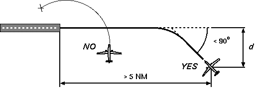
Requirements of the auto-landing.
The figure above illustrate the final approach to the runway. The optimal distance from the LOCATOR plane should be large enough to allow to the aircraft to attain the alignment to the LOCATOR with only a turn at the rate of 1.5°/s:
d ≥ (1 - cos(A)) v / 94
where v is the current TAS (knots). For example, with an angle of incidence of A=30° and v=170 kt the distance would be 0.24 NM. By the contrary, crossing the LOCATOR plane with an angle near to 90° at little distance from the runway, would force the AL to do several turn maneuvers, often ending with a misalignment and a missing approach.
Disabling the AL. The AL can be disabled intentionally pressing Shift-L again. The AL gets also disabled automatically when any of these events occurs:
Detailed description on how the AL works. The exact sequence of the events depends on several factors. For brevity we will indicate with FLARE_ALT the altitude over the runway at which the flare maneuver starts, V is the current speed, :
FLARE_ALT = 0.375 ft/kt * V
so, for example, landing at 160 kt the flare maneuver starts when the radar altimeter indicates 60 ft from the terrain. We will also indicate with V_TOUCHDOWN the airspeed indicated when the main gear hit the runway. The exact sequence of events is as follow:
1. Keep current altitude until the GS path is intercepted. Adjust heading according to the CDI.
2. Once the GS has been intercepted, start descending at the standard rate of −3 DEG. If the GS has a different angle, the resulting GS error will guide the AL to the correct descending ratio. Continue to follow the LOCATOR, adjusting the heading.
3. When the altitude as indicated by the radar altimeter becomes less than 250 ft, the GS signal is assumed to be unreliable and the aircraft keeps its attitude and continues following a ballistic descent at the standard descending rate of −3 DEG.
4. When the altitude indicated by the radar altimeter becomes less than FLARE_ALT, the flare maneuver starts. Raise nose so to keep a descending rate of −1 DEG. Ensure wheel brakes are disabled.
5. When the altitude as indicated by the radar altimeter is less than 0.5*FLARE_ALT disable engine auto-throttle and hold current power setting. The speed begins to reduce.
6. When both the wheels of the main landing gear hit the ground, grab current airspeed V_TOUCHDOWN, as it will used for reference in the rest of the procedure. The speed brakes are fully extended, if available. If the thrust reverse device is available, deploy and set engine power to 75%. Otherwise, set engine idle. Disable auto-pilot and keep current pitch angle.
7. For tricycle landing gear, immediately lower nose wheel. For bicycle landing gear, hold current pitch until speed drops under 85% V_TOUCHDOWN, then begins lowering the tail wheel.
8. For tricycle landing gears, when all the wheels are in contact with the terrain, enable wheel brakes. If thrust reverse available, brakes are enabled only below 50% V_TOUCHDOWN.
9. At 40% V_TOUCHDOWN, if thrust reverse device available, set engine idle.
10. At 20% V_TOUCHDOWN disable AP, AL, AW and retract thrust reverser, leaving only the brakes on.
 The auto-turn block (AW) control the rate of the turn and it is mostly
used by the AN and AL. The pilot can engage manually the AW to perform
standard turns at 1.5 and 3°/s or also 0°/s to keep the current
heading. The involved keys are:
The auto-turn block (AW) control the rate of the turn and it is mostly
used by the AN and AL. The pilot can engage manually the AW to perform
standard turns at 1.5 and 3°/s or also 0°/s to keep the current
heading. The involved keys are:
<turn left at 3°/s
,(comma) turn left at 1.5°/s
|(vertical bar) stop turning and hold heading
.(dot) turn right at 1.5°/s
>turn right at 3°/s
/disengage the AW
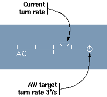
The "MAX BANK" knob set the maximum bank limiter, chosen between 5, 10, 15, 20 and 25 degrees. The AW will never exceed this value.
When the AW is enabled, a little round circle gets displays into the turn-and-sleep indicator giving the feedback of the turn speed the AW is aiming to (see the figure to the right).
The status panel displays 14 lights. The alarm lights blinks alerting the pilot about some serius sub-system failure or other urgent danger:
OIL, HYD1, HYD2: hydraulic subsystem failures.
GEN1, GEN2: power sources failure.
FLAP: flaps failure.
SPBRK: speed brake failure.
RADAR: radar failure.
TEWS: TEWS failure.
HUD: HUD failure.
G-LOAD: above 75% maximum positive or negative wings load.
Status and warning lights does not blink and are alerts to the pilot:
FUEL: fuel tank below 15% maximum capacity.
SPD BRK: speed brakes engaged.
BRAKES: wheel brakes are on.
The ACM radar system has a field of view in Normal mode of 120 degrees laterally and vertically from the front of the aircraft. The F-16 radar set's range is about 80 NM. All aircraft within that range and field of view will appear as a box on the radar display
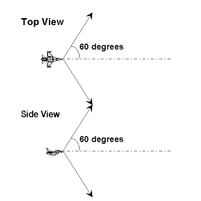
Radar coverage.
The ACM radar display presents a forward looking view of radar targets. Think of it as a television monitor connected to a forward-pointing TV camera that has a very wide angle lens.
If any objects are close enough to be radar-visible, the set will automatically lock onto the nearest threat. With radar lock acquired, your display will provide detailed information about the locked, or "primary", target's disposition. A primary target appears as a filled diamond on the radar display -- the display provides information on the primary target's range and altitude, as well as it's current heading, your desired relative heading to intercept and the rate of closure of your two aircraft.
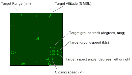
The ACM radar display.
The radar set's ability to establish a positive lock on a target extends for a shorter range than the radar's maximum detection range -- radar lock is limited to about 60 NM on the F-16 and 30 NM on the MiG-29.
If multiple targets are plotted on your radar display, you can lock onto other targets by pressing the target reject key (q).
The radar on/standby key (R) can be used to toggle your radar set between its normal operating mode and a standby state. When your radar is in standby mode, your aircraft emits no radar energy and can be more difficult to detect.
Fighters are Equipped with a special device called a Radar Warning Receiver (RWR). It's display is the round "CRT" to the left of the radar display. It works much like a radar detector that you can buy for your car. The receiver can detect radar emissions from other aircraft and will plot a box on the RWR display representing the relative direction of that radar threat. Opposing team’s radar emissions appear as filled boxes. Friendly aircraft appear as open boxes. This receiver cannot detect aircraft that have their radar emissions directed away from your aircraft, nor is it capable of detecting aircraft that have their radar sets turned completely off.
Your aircraft is equipped with heat-seeking missiles and a 20-millimeter cannon. Weapon information is displayed in the lower left-hand corner of your HUD. Different weapons may be selected by pressing mouse button 3. The currently selected weapon is fired by pressing mouse button 2.
The missiles are patterned after U.S. AIM-9M Sidewinders and AIM-120 AMRAAM. They can detect infrared (IR) targets at any aspect (not just from the rear).
The range of these missiles varies dramatically with the altitude and closure rate. The missile subsystem couples with your radar set to provide time-to-impact information.
This missile has a solid rocket motor that burns for about 8 seconds (AIM-9M) or 15 seconds (AIM-120). After burn-out, it will still track towards its intended target but may lose speed too rapidly to catch it. Your heat seeking missiles don't arm themselves until one second (AIM9M) or three seconds (AIM-120) after launch. Because of that, you should not fire at a target for which the flight time is less than the arm time.
Beware! clouds are opaque to IR. If the target hides in the clouds, the missile loses lock and continues flying ballistically, possibly missing the target.
Missile status discretes and their meanings:
ARM --
No target acquired on the radar.ARM 125
Missile's seeker has not yet acquired the target in its field of view; time to target 125 seconds.LOCKED 18
Missile locked on target and ready to fire; time to target 18 seconds.IN RANGE 2
Target too close; time to target smaller than arm time.
Cannon can be used to engage targets at closer range. Your cannon is modeled after the U.S. M61-A1 Vulcan. Aircraft typically begin a mission with 500 rounds of ammunition; the cannon fires at 3000 rounds per minute so you only have enough ammunition for a ten-second continuous burst -- use it carefully.
When cannons are selected, the HUD is in Lead Computing Optical Sight (LCOS) mode. On the HUD, a circular aiming reticle is displayed. The HUD couples with the radar set to provide a visible cue of the target's current range. The aiming reticle is surrounded by 12 ticks. An inner arc represents the current range to the target: each arc tick represents 1000 feet of distance. The aiming reticle moves across the HUD to show a good aiming point based on the target's range and your aircraft's pitch and turn rate. If the range is large and or your pitch and turn rates are fast, you may see no reticle at all: the aiming point is simply out of the HUD's field of view.
An unmoving cross (a "+") will be displayed on the HUD in LCOS mode. This marker denotes the boresight of the cannon -- the direction that the cannon's barrel is actually pointing.
Figure 6 (missing!) shows another example of what you might see in a dogfight. All planes are turning hard to the left at a relatively low speed. You are in LCOS mode and see that the reticle is positioned ahead of the intended target. To get the kill, simply relax the turn long enough to get into position and then take the shot.
You fighter may be equipped with one or more standard Mark 82 (MK-82) drop bombs. If so, then selecting that weapon with the right mouse button displays the CCIP sighter. The circle indicates the estimated hit point if the bomb get dropped right now with the left button of the mouse. A line joinging the flight path marker to the circle helps aligning the target point while the aircraft dives.
Currently only the SU-30 model is equipped with drop bombs; you may change this setting by adding drop bombs to any other fighter by changing its configuration file as explained in this manual.
Drones are automated opponent aircraft. They are created by pressing the
l key. Drones aggressiveness setting (see option -da)
controls how hard a drone aircraft will attempt to maneuver to attack
other planes. For example, a setting of 0.7 means the drone will maneuver
pulling "G" up to the 70% of its maximum structural vertical limit (see
the parameters MaxLoadZPositive and MaxLoadZNegative); if
the fighter supports up to 10g of positive vertical acceleration with nearly
empty tank, it will reach 7g of positive vertical acceleration.
With an aggressiveness factor too low (probably 0.2 or less) the aircraft will hardly sustain its own weight and will crash on the ground without even try to fly. With a value near 1.0 or greater your opponent drone will fly very close to its structural limit and may suffer a sudden tragic fatal structural failure... Values between 0.7 and 0.9 will usually make for an interesting opponent.
I don't really know what this "stealth" mode is and what it is intended to do, but apparently it is not working anymore. Any help appreciated. - U.S.
ACM’s stealth mode allows users to monitor out-the-window views for any aircraft active in an exercise.
$ acm -stealth
In stealth mode, the radar display is used to display DIS entity id’s of aircraft participating in the exercise. To select and aircraft to follow, use the mouse to click on one of these identifiers. The entity id of the aircraft you are following will be highlighted in magenta.
DIS Entity ID
  50,1,1
  50,1,2
* 50,6,1
If there is a large number of entities in an exercise, use the PAGE UP and PAGE DOWN keys to scroll through the list.